Recovery System Design
DESIGN OF A PARACHUTE RECOVERY AND LANDING SYSTEM
This chapter deals with the design of a parachute recovery and landing attenuation system for a military reconnaissance drone. The prime emphasis in the design of this system is on undamaged recovery of the drone from the total flight performance envelope during the development and test phase, on undamaged recovery after a completed mission during military operations, and on multiple use of the recovery system. An engineering team conducts performance and system analyses and chooses what recovery concept to use, what types of parachutes to select for high-speed deceleration and for final recovery, and what impact-attenuation system is best for the particular application. This chapter covers the selection process for concepts and components. Different engineers may make different selections based on experiences with particular types of parachutes or deployment concepts; experience is always a viable reason for selecting a particular approach. However, using the selection criteria shown in Figure 2-6. the designer must put reliability of operation, undamaged recovery, reusability of the landing system, and minimum weight and volume at the top of the list of requirements.
7.1 REQUIREMENTS
7.1.1 System Requirements
An unmanned air vehicle used for military reconnaissance must be recovered after a completed mission in rough terrain, undamaged and ready for multiple reuses. The recovery system must be able to
- Recover the air vehicle after the completed mission when the vehicle has landed in rough terrain at altitudes from sea level to 5000 feet.
- Recover the drone during the engineering test phase from all controlled and uncontrolled flight conditions.
- Serve as a range-safety device to prevent the air vehicle from leaving the boundaries of the test range.
The air vehicle has a takeoff weight of 7200 pounds and a landing weight, after the completed mission, of 4800 pounds. Undamaged landing shall be possible in rough terrain with rocks up to 8 inches in diameter. Replacement parts and refurbishment cost shall be kept to a minimum.
7.1.2 Requirements for Normal Operation
| Drone weight at recovery after completed mission | Wd = 4800 lb |
| Recovery velocity | vo = 150 to 200 KEAS |
| Minimum recovery altitude | Ho = 2000 ft above ground level (AGL) |
| Maximum ground level | H = 5000 ft |
| Maximum allowable total parachute force | Fo = 16,000 lb |
| Maximum allowable impact deceleration at landing | a = 9.0 g's |
7.1.3 Requirements for Emergency Operation
Emergency operation includes recovery during the test phase from takeoff to landing and also includes recovery for range-safety reasons.
| Drone weight at takeoff | Wdmax = 7200 lb |
| Maximum recovery velocity at mean sea level (MSL) | vo = 490 KEAS |
| Maximum recovery velocity at 38,000 to 50,000 ft altitude | vo = 1.5 Mach |
| Maximum dynamic pressure | qmax = 812 lb/ft2 |
| Maximum allowable parachute force | Fo = 22,000 lb |
7.1.4 Requirements Analysis
Three primary requirements pace the design of the recovery system:
- The drone must be able to land in rocky but level terrain without damage.
- Refurbishment cost and time shall be kept to a minimum.
- Recovery must be possible from all flight conditions during the flight test phase, including cases where the out-of-control drone flies off the range.
7.2 LANDING ANALYSIS AND IMPACT-ATTENUATION SYSTEM
7.2.1 Landing Analysis
Three known recovery concepts prevent damage during landing in rocky terrain:
- Midair retrieval.
- Dual air bags or dual frangibles.
- Retrorockets combined with small, nondeflatable air bags.
The need for retrieval helicopters or retrieval aircraft makes Method 1, midair retrieval, impractical. The other two methods are affected by the deceleration distance required to meet the 9-g limit.
In section 6.8 of this manual, the required deceleration distance(s) is determined to be
where
= velocity of the drone descending on the parachute (rate of descent), ft/s
= permissible impact velocity, ft/s
= acceleration of gravity, ft/s2
= effectiveness of the impact attenuation system used, dimensionless
Failed to parse (Conversion error. Server ("https://wikimedia.org/api/rest_") reported: "Cannot get mml. Server problem."): {\displaystyle n} = allowable impact deceleration, ratio
Figure 6-68 of Chapter 6 shows the range of various impact attenuation systems as a function of rate of descent and allowable ground impact deceleration. The information indicates that air bags may be the most practical concept for this application. A cursory analysis indicates that a rate of descent of 25 ft/s at 5000 feet: altitude will result in a close to optimum weight ratio of the combined parachute air bag system (see Figure 6-83). Properly designed air bags will have an effectiveness of 65% as shown in the stroke-pressure diagram in Figure 6-78 and allow ground contact or final velocity of close to 0 ft/s.
With these assumptions, the required effective air bag deceleration stroke is obtained.
This deceleration distance is too short for a parachute retrorocket system because of the required timing accuracy and rocket burning time. Retrorocket systems are most practical for deceleration distances greater than 4 or 5 feet. Crushable and frangible impact attenuators are suitable for deceleration distances of less than 15 inches. Air bag systems work best for deceleration distances of 24 to 48 inches. The original assumption that an air bag concept maybe the most practical approach for this air vehicle is therefore confirmed.
7.2.2 Impact Attenuator System
The design of impact attenuator systems is discussed in section 6.8 of this manual. Figure 7-1 shows the reconnaissance drone and the air-bag attenuator systems that consist of two deflatable, two-compartment wing-bag bags (A); a single-compartment, deflatable nose bag (B); and a nondeflatable nose-buffer bag (C). The wing bags, the primary energy absorbers, need the already calculated 24-inch effective-deceleration stroke. For design reasons, 33 inches must be added to the bag height, 19 inches for the distance from the wing underside to the underside of the jet airducts, 10 inches for ground clearance, and 4 inches for bag bottom curvature. These additions result in a total bag height of 57 inches. To ensure landing stability, an air bag height-to-diameter ratio of 1.25 is selected for the two wing bags, resulting in a bag diameter of 48 inches. The cross-hatched lower part of the two wing bags (see Figure 7-1) deflates at impact, but the upper part stays inflated and keeps the drone off the ground. The nose bag, B, helps to absorb the impact and deflates, and the nose of the drone comes to rest on the nondeflatable buffer bag, C. All air bags are inflated from 3000 psi nitrogen containers using aspirators for a 50/50 nitrogen air mixture. The air bags are pre-pressurized to 2 psi for full bag inflation prior to landing. Multiple blowout valves consisting of staggered blowout rubber disks around the circumference of the air bags control the bag deflation to stay within the 9-g deceleration limit.
The weight of the impact-attenuation system-air bags, nitrogen containers, plumbing, and A/C containers-is estimated from section 6.7 to be 2.2% of the total drone weight, or 105.6 pounds. The air bags should be stored in containers that can be easily removed from the drone for repacking. Air bags must be deployed after the main parachutes are fully open to prevent air-bag damage caused by high dynamic pressure. Air-bag deployment begins with simultaneous pyroejecting of the removable air-bag-container covers and opening of the nitrogen-container valves. The wing bags, the primary nose bag, and the nose-buffer bag inflate. At ground contact, the bags compress, increasing the pressure inside the bags. At a preselected pressure level, the blowout valves (rubber disks, metal disks, or rubber-type sleeves) open and limit the maximum drone deceleration to the preselected level.
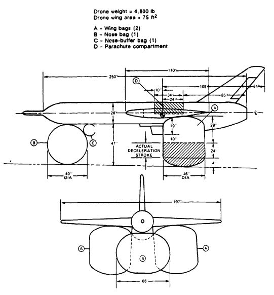
The drone comes to rest on the upper compartment of the two wing bags and the nose-buffer bag.
The pressure increases in the bags at ground contact, in connection with a short time delay (0.5 to 1.0), may be used as a signal for disconnecting the main parachutes to prevent wind-dragging of the drone.
7.3 MAIN PARACHUTE SYSTEM
7.3.1 Main Parachute System Requirements
Weight to be recovered:
| Operational | Wd = 4800 lb |
| Test phase | Wd max = 7200 lb |
| Recovery velocity | vo = 150 to 200 KEAS |
| Recovery altitude | Ho = 2000 ft AGL |
| Maximum ground level | H = 5000 ft |
| Rate of descent | ve = 25 ft/s at 5000 ft |
| Stability | Oscillation of not more than ± 5 deg |
| Maximum total parachute force | F ≤ 16,000 lb = 3.3 g* |
Maximum recovery-system weight and volume are prime requirements.
7.3.2 Parachute Assembly Section
Section 2.4 defines the criteria for parachute type selection. Requirements for low weight and volume rule out the low-drag slotted parachutes (ribbon, ringslot, and ringsail) as well as guide-surface and cross parachutes (see Tables 5.2 and 5.3). Parachute deployment past the vertical stabilizer rules out a single parachute in favor of a cluster of two parachutes deployed independently left and right of the vertical stabilizer.
No cluster experience is available with annular or cross parachutes, and no reefing experience is available with annular parachutes. Cross parachutes cannot be reefed to the low reefing ratios required for this application. Extended-skirt and polyconical parachutes have been used successfully in clusters of large, reefed parachutes.
A cluster of two conical full extended skirt parachutes is most suitable for this system. In section 5.2, Figures 5-24 and 5-25 show that properly designed extended-skirt parachutes have drag coefficients equal to 0.8 to 0.9 in the 20- to 25-ft/s rate of descent range. Available data (Reference 5.23) indicate that a cluster of two extended-skirt parachutes is sufficiently stable for use with air bags. Extended-skirt parachutes have a low opening-force coefficient of 1.4, compared to an opening-force coefficient of 1.8 for conical and triconical parachutes. Extended-skirt parachutes can also be reefed to low reefing ratios, a requirement for final descent parachutes (see Chapter 5, Figure 5-72).
7.3.3 Parachute Diameter
The rate of descent at 5000 feet altitude was selected to 25 ft/s (see section 7.3.1). The
equivalent rate of descent at sea level is:
at 5000 ft. is 0.9283 (see Table 3-3); therefore,
The required parachute drag area, for one parachute is calculated
and the single parachute drag area
The drag coefficient, CDo, for a conical full extended skirt parachute with a 23.2-ft/s rate of descent and a suspension-line ratio, Le/Do, of 1.0 is obtained from Figure 5-25:
In a cluster of two parachutes, a drag loss of 2% is experienced (see Figure 5-110). Longer suspension lines can somewhat compensate for the loss. Choosing a suspension line/canopy ratio of Le/Do = 1.15 (see Figure 5-20) results in a drag gain of 1.5%. A drag coefficient = 0.9 is selected for this application. If the drag coefficient is 0.9, the parachute surface area, , is
and the nominal parachute diameter, ,is
A suspension-line ratio of 1.15 is selected. This is the longest practical length for extended skirt parachutes (see Figure 5-20).
The length of the riser, Lr, depends on its installation in the drone; the riser should be long enough to extend beyond the fuselage and vertical stabilizer of the drone (see Figure 7-2), which gives the final configuration of the parachute cluster, including risers and parachutes.
7.3.4 Parachute Deployment System
A cluster of two main parachutes is selected and deployed left and right of the vertical stabilizer to avoid hang-up or damage of a single parachute by the vertical stabilizer. Each parachute needs its own extraction and deployment system to properly deploy past the stabilizer and to avoid interference with the other main parachute during deployment and inflation.
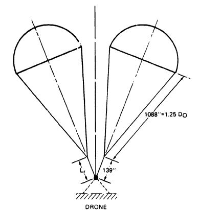
Two fast-opening extraction parachutes are used on each main parachute. Stable parachutes will minimize interference, during deployment. Experience with past recovery systems has shown that the most positive deployment is obtained by forced ejection of the extraction or pilot chutes into good airflow past the vertical stabilizer by either mortar or drogue gun ejection. A mortar can eject large, heavy parachutes but creates large reaction forces and needs considerable space for installation. Drogue gun ejection is effective, but is limited to the deployment of small, lightweight parachutes such as pilot chutes. Drogue gun ejected pilot chutes are selected for initiating main parachute deployment. To ensure proper clearance of the vertical stabilizer, the pilot chutes are ejected 45 degrees upward, backward and outward past the vertical stabilizer. The parachute installation in the drone fuselage requires crosswind deployment and therefore forced ejection of the main parachute deployment bags. Four different methods have been used successfully to accomplish forced ejection: (1) using ejector springs enclosed in a textile cylinder. (2) gas-inflating nonporous ejector bags, (3) catapulting the bag out of the compartment, or (4) using a lift-web arrangement as discussed in section 6.1.
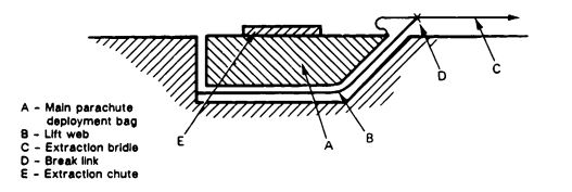
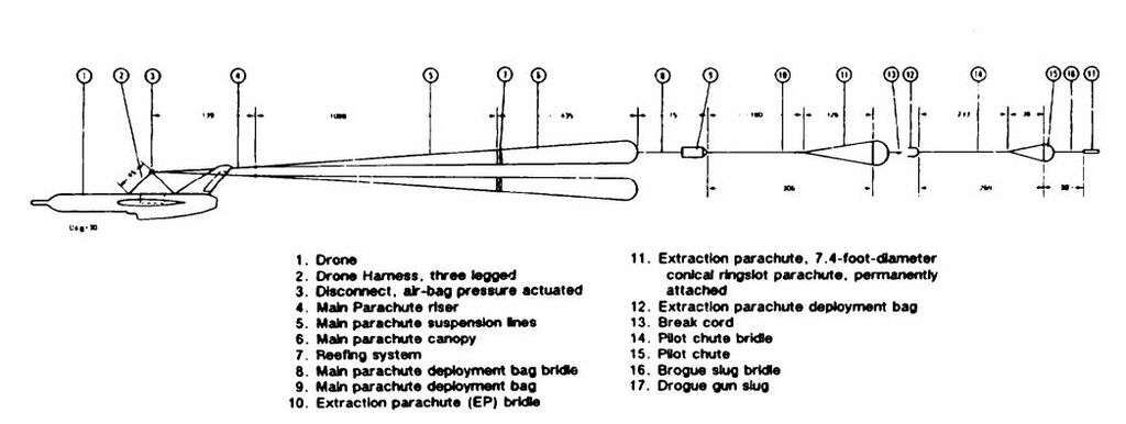
The deployment system selected consists of a drogue gun deployed pilot chute, an extraction parachute, and a main parachute deployment bag lifted from the parachute compartment by lift webs. When the hinged compartment doors open, two drogue gun slugs are fired 45 degrees upward and aft; each slug deploys a pilot chute sufficiently behind the drone into good airflow. These pilot chutes in turn extract two extraction chutes stowed on top of the main parachute deployment bags. The extraction chutes extract and deploy the two main parachutes left and right of the vertical stabilizers. Lift webs and unsymmetrical bag handles lift the main parachute bags out of the drone compartment and extract the main parachute past the vertical stabilizer (see Figure 7-3).
7.3.5 Extraction Parachute Assembly
The two extraction parachutes must properly deploy the two main parachutes. The size of the extraction parachutes and their location in the wake of the drone is determined as follows:
1. The ratio of the drag area of the extraction parachute, , to the drag area of the main parachutes, , has been evaluated for various deployment velocities (see section 6.3, Table 6-5). For the 150- to 200-KEAS-velocity range, a ratio of 0.007 is selected.
2. The leading edge of the extraction parachute must be placed 6 forebody diameters behind the drone to ensure good inflation in the wake of the forebody.
The size of the extraction parachute is determined to be
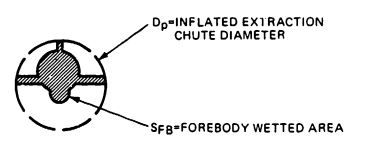
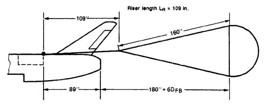
The forebody diameter of the noncylindrical drone fuselage, shown in Figure 7-4 and discussed in section 5.2, is used to determine the location of the extraction parachute.
The equivalent forebody diameter is determined from the netted forebody area
The distance between the tail of the drone and the leading edge of the extraction parachute is
The selected extraction parachute is a stable, reasonably high drag ringslot parachute with long suspension lines. A ringslot parachute was used as an extraction chute for each Apollo main parachute. Table 5-2 in section 5.1 gives, for a ringslot parachute, a of 0.56 to 0.65. A medium porosity canopy is selected with a =0.65. A medium porosity canopy is selected with a = 0.65. Using suspension lines with a Le/Do ratio of 2 increases the drag coefficient by 10% (see Figure 5-20). Therefore, .
The extraction parachute to forebody diameter ratio is
and the distance behind the forebody-to-forebody ratio is
resulting in a drag loss of 13% (see Figure 5-21) and a final
The canopy surface area, , is
resulting in a nominal parachute diameter
A stable, 7.4-foot-diameter ringslot parachute is selected. The weight of the ringslot extraction parachute can be estimated from section 6.7 to 2.5 pounds, and the weight of the extraction parachute assembly including riser and deployment bag to 1.5 Failed to parse (Conversion error. Server ("https://wikimedia.org/api/rest_") reported: "Cannot get mml. Server problem."): {\displaystyle \cdot } 2.5 pounds = 3.75 pounds.
The weight of a single 72.7-foot-diameter main parachute, as determined from section 6.7, is 54 pounds. This weight estimate assumes an efficiently designed main canopy that has a combination of tape and radial seams to carry the radial loads and has other, similar weight-saving design features. The arrangement of the extraction parachute in relation to the drone is shown in Figure 7-5.
7.3.6 Pilot Parachute Assembly
The extraction parachute assembly weight of 3.75 pounds is too heavy to be deployed by a drogue-gun slug; therefore, a small pilot chute is selected for initial deployment by the drogue-gun slug. This pilot chute, in turn, will deploy the extraction parachute.
Evaluation of past good and poor deployments has led to the rule that the extraction force of the pilot chute should be greater than or equal to four times the weight of the unit to be extracted; in this case, the extraction parachute assembly. So that the pilot chute has enough force, a pilot chute is selected that will produce, at the minimum deployment speed of 150 KEAS, an extraction force equal to five times the weight of the extraction parachute assembly: 5 Failed to parse (Conversion error. Server ("https://wikimedia.org/api/rest_") reported: "Cannot get mml. Server problem."): {\displaystyle \cdot } 3.75 pounds = 18.75 pounds.
The minimum dynamic pressure at 150 KEAS is
This results in a pilot chute drag area of
A fast opening, stable, box-type pilot chute, see Figure 6-32, is selected with a drag coefficient of = 0.55. The pilot chute canopy area, , is
and the parachute diameter, Do, is
This is a very small parachute. A 2.0-foot-diameter box-type pilot chute with stabilizer vanes is selected. This pilot chute has a steady extraction force, :
Figure 7-6 shows the pilot chute assembly in relation to the drone, and Figure 7-7 shows the total main parachute subsystem.

7.3.7 Main Parachute Forces
7.3.7.1 Requirements
Drone weight ............................................. = 4800 lb
Maximum deployment speed ....................... Failed to parse (Conversion error. Server ("https://wikimedia.org/api/rest_") reported: "Cannot get mml. Server problem."): {\displaystyle v_{o}} = 200 KEAS
Minimum deployment speed ........................ = 150 KEAS
Maximum allowable total parachute force
(two main parachutes) ................................ = 16,000 lb
Deployment altitude .................................. H = 2000 to 7000 ft.
7.3.7.2 Velocity-Altitude Profile
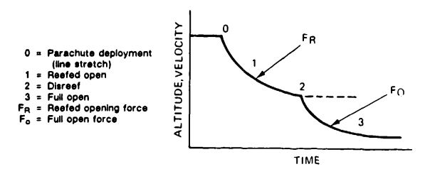
Section 5.5 states that the maximum opening force of the main parachute occurs at maximum deployment altitude. Figure 7-8 shows a velocity-altitude-versus-time profile for a typical vehicle recovery system.
The maximum dynamic pressure, , occurs at the 200-KEAS deployment velocity
Failed to parse (Conversion error. Server ("https://wikimedia.org/api/rest_") reported: "Cannot get mml. Server problem."): {\displaystyle q_{o}=q_{(200KEAS)}={\frac {v^{2}}{296}}={\frac {200^{2}}{296}}=135.14\ lb/ft^{2}}
True velocity at maximum deployment altitude in feet per second is
7.3.7.3 Force Calculation Methods
The opening forces of the reefed and full-open main parachutes will be determined by three different methods described in section 5.4.6.
1. The method is accurate for high canopy loading parachutes, such as drogue chutes, and for the first stage of reefed parachutes. However, opening forces calculated by this method may be only ± 20% accurate for unreefed main descent parachutes and for the disreef stage of large main parachutes.
2. The Pflanz method is quite accurate for all conditions including high altitude but neglects the effect of gravity. Parachutes opened in vertical descent will have a 1-g (one weight unit) higher force than calculated. It is necessary to calculate the canopy filling times for the various reefed stages (see section 5.4.3) and to determine the drag-area-versus-time profile for the specific parachute (see section 5.4.4). This method permits the investigation of variations in filling times and drag-area-versus-time profiles.
3. The force-trajectory-time computer method includes the effects of altitude, gravity, and changing trajectory angle. This method requires determination of a drag-area-versus-time profile for the entire parachute opening sequence (see Figure 5-52). Computers permit multiple runs with changes in times, drag-area-versus-time profiles, starting velocities, and altitudes.
7.3.7.4 Reefed Opening Forces
When the method is used, the opening force of the reefed parachute, FR, is
where:
Failed to parse (Conversion error. Server ("https://wikimedia.org/api/rest_") reported: "Cannot get mml. Server problem."): {\displaystyle q_{0}=dynamic\ pressure\ at\ line\ stretch\ =135.14\ lb/ft^{2}\ } (see section 7.3.7.2)
(see Table 5-2)
(see Figure 5-48)
The allowable drag area of a single, reefed main parachute is
Failed to parse (Conversion error. Server ("https://wikimedia.org/api/rest_") reported: "Cannot get mml. Server problem."): {\displaystyle (C_{D}S)_{R}={\frac {F_{R}\ allowable}{q_{o}\cdot C_{x}\cdot X_{1}}}}
FR allowable = 8000 pounds (see section 7.3.7.1). C, for reefed opening of extended-skirt parachutes is 1.0 to 1.1 (see Figure 5-52). XI is obtained from Figure 5-48 as a function of canopy loading, W/(DS)R, that is calculated under the assumption that the reefed drag area of one main parachute is about 2.5% of the fully open drag area. Therefore, the canopy loading of the reefed parachute is
For this canopy loading, Failed to parse (Conversion error. Server ("https://wikimedia.org/api/rest_") reported: "Cannot get mml. Server problem."): {\displaystyle X_{1}} is obtained from Figure 5-48 and is 0.86, thus
Failed to parse (Conversion error. Server ("https://wikimedia.org/api/rest_") reported: "Cannot get mml. Server problem."): {\displaystyle (C_{D}S)_{R}={\frac {8000lb}{135.14\ lb/ft^{2}\cdot 1.1\cdot 0.86}}=62.58ft^{2}}
This reefed drag area is less than 2% of the drag area of the full-open main parachute and may be too small for obtaining reliable, fully reefed canopy inflation. Therefore, a 2.2% drag area ratio is selected.
The opening forces for this larger reefed drag area mutt be calculated. The canopy loading, , of the reefed main parachute is
For this canopy loading, Figure 5-48 shows a force-reduction factor, Failed to parse (Conversion error. Server ("https://wikimedia.org/api/rest_") reported: "Cannot get mml. Server problem."): {\displaystyle X_{1}} , of 0.75. The reefed opening force is now calculated
This force is higher than the allowable force of 8000 pounds per parachute (see Section 7.3.7.1).
When the second calculation method, the Pflanz method, is used, the reefed opening force is:
Failed to parse (Conversion error. Server ("https://wikimedia.org/api/rest_") reported: "Cannot get mml. Server problem."): {\displaystyle F_{R}=(C_{D}S)_{R}\cdot q_{1}\cdot C_{x}\cdot X_{1}}
Failed to parse (Conversion error. Server ("https://wikimedia.org/api/rest_") reported: "Cannot get mml. Server problem."): {\displaystyle X_{1}} is a function of the ballistic coefficient, A:
In this equation, known values are W, (), g, and Failed to parse (Conversion error. Server ("https://wikimedia.org/api/rest_") reported: "Cannot get mml. Server problem."): {\displaystyle v_{o}} .
The mass density of air, p, at a 7000-foot altitude is
(see Table 3-3)
Canopy inflation time, , is calculated as follows (see Section 5.4.3):
Failed to parse (Conversion error. Server ("https://wikimedia.org/api/rest_") reported: "Cannot get mml. Server problem."): {\displaystyle A={\frac {2(2400)}{(82.37\ ft^{2})(0.00192695)(31.28)(0.49\ s)(374.9\ ft/s)}}=5.26^{*}}
is appropriate for reefed inflation (see Figure 5-39).
(See Figure 5-51)
It is interesting to investigate the effects of changing the canopy filling time ± 25% and changing the slope of the drag area profile on the parachute opening force. For the change of the drag area slope, a profile factor of n = 1.0 instead of n = ½ (see Figure 5-1) is selected. The resultant change in opening force is shown in Table 7.1.
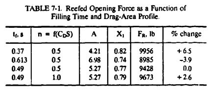
Force data obtained with the force-trajectory-time computer method are shown in the force summary in section 7.3.7.5.
7.3.7.5 Main Parachute Disreef Opening Forces
A short reefing time, , helps to limit altitude losses; however, in clusters, sufficient reefing time is required to permit all parachutes to reach full reefed inflation before disreef. To save trajectory time, the reefed parachute is disreefed at a dynamic pressure of 10 to 20% higher than the terminal reefed dynamic pressure. Therefore,
Failed to parse (Conversion error. Server ("https://wikimedia.org/api/rest_") reported: "Cannot get mml. Server problem."): {\displaystyle q_{2}=1.1{\frac {W}{(C_{D}S)_{R}}}} (Figure 7-8)
, and
Failed to parse (Conversion error. Server ("https://wikimedia.org/api/rest_") reported: "Cannot get mml. Server problem."): {\displaystyle v_{2}={\sqrt {q\cdot y}}{\frac {1}{\sqrt {\sigma }}}={\sqrt {24.03(840)}}\cdot 1.1106=157.8ft/s^{*}} (see Figure 5-112)
Parachute opening force, Failed to parse (Conversion error. Server ("https://wikimedia.org/api/rest_") reported: "Cannot get mml. Server problem."): {\displaystyle F_{o}} , by the method:
Failed to parse (SVG (MathML can be enabled via browser plugin): Invalid response ("Math extension cannot connect to Restbase.") from server "https://wikimedia.org/api/rest_v1/":): {\displaystyle X_1=f[\frac{W}{C_DS}]}
Failed to parse (SVG (MathML can be enabled via browser plugin): Invalid response ("Math extension cannot connect to Restbase.") from server "https://wikimedia.org/api/rest_v1/":): {\displaystyle \frac{W}{(C_DS)_{2-3}}=\frac{2400\ lb}{(3744-82.4)ft^2}=\frac{2400\ lb}{3661.3\ ft^2}=0.656\ lb/ft^2}
Failed to parse (SVG (MathML can be enabled via browser plugin): Invalid response ("Math extension cannot connect to Restbase.") from server "https://wikimedia.org/api/rest_v1/":): {\displaystyle X_1} for 0.656 is 0.07 and
Failed to parse (SVG (MathML can be enabled via browser plugin): Invalid response ("Math extension cannot connect to Restbase.") from server "https://wikimedia.org/api/rest_v1/":): {\displaystyle F_o = (3631)(23.94)(1.30)(0.07)=7910}
Opening force by the Pflanz method:
Failed to parse (SVG (MathML can be enabled via browser plugin): Invalid response ("Math extension cannot connect to Restbase.") from server "https://wikimedia.org/api/rest_v1/":): {\displaystyle F_o=(C_DS)_{3} \cdot q_2 \cdot C_x \cdot X_1}
Failed to parse (SVG (MathML can be enabled via browser plugin): Invalid response ("Math extension cannot connect to Restbase.") from server "https://wikimedia.org/api/rest_v1/":): {\displaystyle X_1=f(A)}
Failed to parse (SVG (MathML can be enabled via browser plugin): Invalid response ("Math extension cannot connect to Restbase.") from server "https://wikimedia.org/api/rest_v1/":): {\displaystyle A=\frac{2W}{(C_DS)_{3} \cdot \rho \cdot g \cdot t_f \cdot v_2}}
Known variables are Failed to parse (SVG (MathML can be enabled via browser plugin): Invalid response ("Math extension cannot connect to Restbase.") from server "https://wikimedia.org/api/rest_v1/":): {\displaystyle W,\ \rho,\ g, and\ v_2. }
Failed to parse (SVG (MathML can be enabled via browser plugin): Invalid response ("Math extension cannot connect to Restbase.") from server "https://wikimedia.org/api/rest_v1/":): {\displaystyle (C_DS)_{3} = (C_DS)_o - (C_DS)_R = 3744 - 82.3 = 3661.7 ft^2}
A 6-second reefing time, Failed to parse (SVG (MathML can be enabled via browser plugin): Invalid response ("Math extension cannot connect to Restbase.") from server "https://wikimedia.org/api/rest_v1/":): {\displaystyle t_R}
, is selected, and an altitude loss during the reefed stage of 500 feet is calculated (from 7000 feet to 6000 feet). Density, Failed to parse (SVG (MathML can be enabled via browser plugin): Invalid response ("Math extension cannot connect to Restbase.") from server "https://wikimedia.org/api/rest_v1/":): {\displaystyle \rho}
, at 6500 feet is 0.0019569 slugs/ft^3.
The filling time, Failed to parse (SVG (MathML can be enabled via browser plugin): Invalid response ("Math extension cannot connect to Restbase.") from server "https://wikimedia.org/api/rest_v1/":): {\displaystyle t_f}
, is obtained by
Failed to parse (SVG (MathML can be enabled via browser plugin): Invalid response ("Math extension cannot connect to Restbase.") from server "https://wikimedia.org/api/rest_v1/":): {\displaystyle t_f=t_{2-3}=\frac{nD}{v_2} \cdot \sqrt{\frac{(C_DS)_o-(C_DS)_R}{(C_DS)_o}}}
From Table 5-6 in section 5.4.3, a canopy fill constant n = 7Failed to parse (SVG (MathML can be enabled via browser plugin): Invalid response ("Math extension cannot connect to Restbase.") from server "https://wikimedia.org/api/rest_v1/":): {\displaystyle ^* } is selected; therefore,
Failed to parse (SVG (MathML can be enabled via browser plugin): Invalid response ("Math extension cannot connect to Restbase.") from server "https://wikimedia.org/api/rest_v1/":): {\displaystyle t_f = \frac{7(72.7)}{155.6} \cdot\sqrt{\frac{3744-82.4}{3744}}=2.80(0.988)=2.73\ s^* }
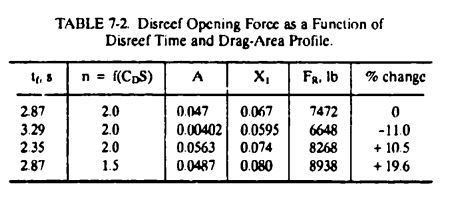
Failed to parse (SVG (MathML can be enabled via browser plugin): Invalid response ("Math extension cannot connect to Restbase.") from server "https://wikimedia.org/api/rest_v1/":): {\displaystyle A=\frac{2(4800\ lb)}{(2)(3661\ ft^2)(0.0019569)(32.17)(2.87\ s)(155.6\ ft/s)}=0.0471}
From evaluation of test data, it is known that the drag-area-increase-versus-time of extended-skirt parachutes at disreef occurs in a concave form, denoted in Figure 5-51 by the definition n = 2. For a ballistic parameter A = 0.0471 and a drag area increase in accordance with n = 2, the force reduction factor, Failed to parse (SVG (MathML can be enabled via browser plugin): Invalid response ("Math extension cannot connect to Restbase.") from server "https://wikimedia.org/api/rest_v1/":): {\displaystyle X_1}
is 0.067, and the parachute disreef force, Failed to parse (SVG (MathML can be enabled via browser plugin): Invalid response ("Math extension cannot connect to Restbase.") from server "https://wikimedia.org/api/rest_v1/":): {\displaystyle F_o}
, is
Failed to parse (SVG (MathML can be enabled via browser plugin): Invalid response ("Math extension cannot connect to Restbase.") from server "https://wikimedia.org/api/rest_v1/":): {\displaystyle F_o = (3.661\ ft^2)(21.76\ lb/ft^2)(1.4)(0.067)=7472\ lb}
Results of changing the canopy inflation time, Failed to parse (SVG (MathML can be enabled via browser plugin): Invalid response ("Math extension cannot connect to Restbase.") from server "https://wikimedia.org/api/rest_v1/":): {\displaystyle t_f} , and the drag-area-versus-time profile, n, are shown in Table 7-2.
Reference 5-76, the Pflanz report, provides a more detailed study of the effect of canopy fill time and drag-area-increase-versus-time profile on the magnitude of the parachute force.
Force-Trajectory-Time Computer Method
The program established oy NWC determines as a function of time the parachute forces, the vehicle deceleration, and the space-positioning (trajectory) data in a two-axis system. The method requires a drag-area-versus-time profile for the individual parachutes and the total vehicle system (Figure 7-9). This profile was previously shown in Figure 5-52. Figure 7-9 includes the change in air-vehicle drag caused by the change in vehicle attitude during the parachute opening process.
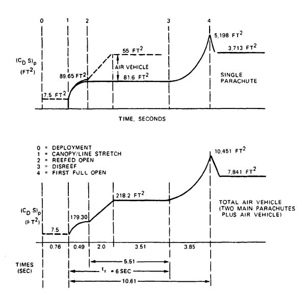
Parachute force data calculated by the three methods are compared in Table 7-3.
7.3.7.6 Comments on Calculated Opening Forces
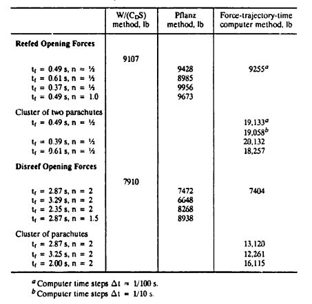
1. The reefed opening force for the single parachute is higher than the contractor-requested maximum allowable force per parachute of 8000 pounds.
2. The average disreef force is approximately 1500 pounds lower than the reefed force. Therefore, it appears logical to lower the reefed force and increase the disreef force. Although this adjustment probably cannot be made within the 8000-pound limit, 8500 pounds appears to be an obtainable goal.
3. To meet the contractor requirement of an 8000-pound maximum force limit per parachute, two-stage reefing is required.
4. It appears practical to determine in drop tests if a 2.0 to 2.1% reefed drag area can be obtained. This drag area would decrease the reefed opening force and somewhat increase the disreef force. However, reaching an average maximum force of less than 8000 pounds appears doubtful.
5. In the calculations, both parachutes are assumed to have equal opening forces. In reality, opening forces of the two parachutes can differ because of variations in filling time, lead-and-lag chute behavior caused by blanketing, and resultant nonuniform canopy inflation.
The fast-opening Apollo ringsail-type main parachutes had a load distribution among the three parachutes of 40-40-20. The individual parachutes, therefore, had to be overdesigned in a 40/33 ratio. However, the total parachute force load taken by the vehicle hard points did not exceed the calculated average load because of the high-low variation of the individual parachutes.
The two slower-opening extended-skirt parachutes used for this application are more uniform in their load distribution. A cursory analysis of available test data indicates that a 55/45 load distribution between the two parachutes and a no-overload condition for the vehicle hard points should be an acceptable load distribution.
A contractor-subcontractor agreement is required to determine whether the individual parachutes should be designed for the 55/45 load variation or whether this overload can be accommodated by the 1.5 safety factor and the additional safety provided by the normal overstrength of textile specification materials.
7.3.7.7 Snatch Forces
The snatch force is caused by the acceleration of the mass of the parachute assembly to the velocity of the forebody (drone). A canopy, partially inflated at line stretch, increases the mass of the parachute by the mass of the air included in the canopy; this can increase the snatch force (mass shock) considerably.
Two principal rules should be followed to keep the snatch force within allowable limits.
1. Keep the parachute canopy closed until line (canopy) stretch occurs by use of a deployment bag or skirt restrictor.
2. Accelerate the mass of the parachute assembly in incremental steps.
Known means of accomplishing these goals are discussed in Chapter 6.1.
The difference between a poor deployment and a deployment that accomplishes the first rule and partially accomplishes the second is illustrated in Figure 5-54, which shows snatch and opening forces for the C-9 parachute with and without the quarter deployment bag. The deployment method outlined in section 7.3.4 should hold snatch forces at a level below the parachute opening forces.
A method for calculating snatch forces is described in Reference 2.2, the 1963 edition of the USAF parachute handbook. The preferred method for calculating parachute deployment, including the snatch force, is contained in J. W. Purvis's AIAA paper, "Improved Prediction of Parachute Line Sail During Lines-First Deployment" (Reference 5.86).
7.3.8 Parachute Stress Analysis
7.3.8.1 Parachute Design Data
A total parachute assembly is shown in Figure 7-10.
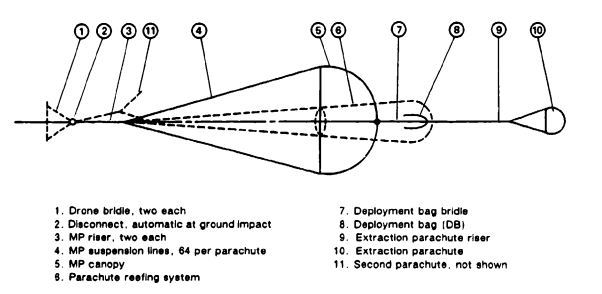
Parachute type: Conical full extended skirt
Diameter: Do = 72.7 ft
Line-length ratio: Le/Do = 1.25; Le = 1083 in.
7.3.8.2 Parachute Forces
The maximum reefed opening force, Failed to parse (SVG (MathML can be enabled via browser plugin): Invalid response ("Math extension cannot connect to Restbase.") from server "https://wikimedia.org/api/rest_v1/":): {\displaystyle F_R} , is 9255 pounds. The maximum disreef opening force, Failed to parse (SVG (MathML can be enabled via browser plugin): Invalid response ("Math extension cannot connect to Restbase.") from server "https://wikimedia.org/api/rest_v1/":): {\displaystyle F_o} , is 7404 pounds. The maximum design force for stressing the parachute assembly, Failed to parse (SVG (MathML can be enabled via browser plugin): Invalid response ("Math extension cannot connect to Restbase.") from server "https://wikimedia.org/api/rest_v1/":): {\displaystyle F_x} , is 9255 pounds.
The forces obtained in computer runs are selected as the most accurate forces for stressing the parachute assembly and its components. Based on multiple computer runs, a diligent choice must be made for the most likable forces.
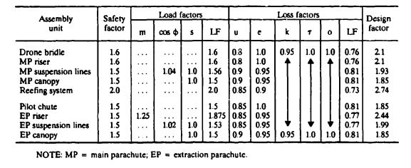
7.3.8.3 Main-Parachute Safety and Design Factors
Section 6.4 is used as a guide for selecting the safety, load, loss, and design factors in Table 7-4.
7.3.8.4 Suspension-Line Selection and Strength
The following guidelines are used for selecting the suspension lines of the main parachutes (Table 7-5).

1. Connection of suspension lines to riser legs and drone hardpoints is made easier if the number of suspension lines are a multiple of 4 or 8.
2. The gore at the skirt should not be wider than 3.5 feet for packing reasons.
3. The canopy should have no fewer than 12 gores to avoid gore distortion during inflation.
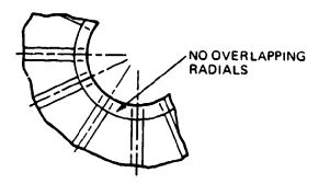
4. Radial ribbons or radial seams should not overlap at the vent; overlapping causes bunching of material and associated sewing problems.
5. The strengths of available suspension-line types may affect the gore selection.
Table 7-5 shows the required suspension line strength and the resultant gore width as functions of the number of gore/suspension lines used.
The width of the gore of the skirt on conical, full-extended-skirt (CFES) parachutes is about 85% of the maximum gore width, Eo.
Sixty-four suspension lines are selected in accordance with MIL-C-7515, Type XI, with 300-pound tensile strength.
This selection provides a margin of safety (MS) of
Failed to parse (SVG (MathML can be enabled via browser plugin): Invalid response ("Math extension cannot connect to Restbase.") from server "https://wikimedia.org/api/rest_v1/":): {\displaystyle MS=\frac{available\ strength}{required\ strength}-1=\frac{300}{281.9}-1=1.064-1=0.064}
The suspension line will be attached to the canopy skirt in a loop connection.
7.3.8.5 Canopy Stress
No precise method has been developed for calculating the stress in a circular, solid-material, bias-construction canopy.
Section 6.4 describes a semi-empirical method for determining the required fabric strength of a solid material canopy in pounds per unit width using the stress in a pressure vessel as an analogy. The stress in a cylindrical vessel, expressed as force per unit length, is
Failed to parse (SVG (MathML can be enabled via browser plugin): Invalid response ("Math extension cannot connect to Restbase.") from server "https://wikimedia.org/api/rest_v1/":): {\displaystyle t_c=\frac{pr}{2}(lb/in.)}
where p is the pressure in the cylindrical vessel and r is the vessel radius. Using this analogy and considering the canopy gore as part of a pressure vessel, the required material strength of the canopy per unit width is obtained
Failed to parse (SVG (MathML can be enabled via browser plugin): Invalid response ("Math extension cannot connect to Restbase.") from server "https://wikimedia.org/api/rest_v1/":): {\displaystyle t_c=\frac{F_o}{\pi D_p12}DS}
where
Failed to parse (SVG (MathML can be enabled via browser plugin): Invalid response ("Math extension cannot connect to Restbase.") from server "https://wikimedia.org/api/rest_v1/":): {\displaystyle t_c} = required material strength in lb/in. width
Failed to parse (SVG (MathML can be enabled via browser plugin): Invalid response ("Math extension cannot connect to Restbase.") from server "https://wikimedia.org/api/rest_v1/":): {\displaystyle F_o} = maximum parachute force = 9255 pounds
Failed to parse (SVG (MathML can be enabled via browser plugin): Invalid response ("Math extension cannot connect to Restbase.") from server "https://wikimedia.org/api/rest_v1/":): {\displaystyle D_p} = inflated parachute diameter - DOC (see Figure 5-78)
Failed to parse (SVG (MathML can be enabled via browser plugin): Invalid response ("Math extension cannot connect to Restbase.") from server "https://wikimedia.org/api/rest_v1/":): {\displaystyle DS} = design factor, 1.85 (see Table 7-4)
Failed to parse (SVG (MathML can be enabled via browser plugin): Invalid response ("Math extension cannot connect to Restbase.") from server "https://wikimedia.org/api/rest_v1/":): {\displaystyle t_c = \frac{9255}{(\pi)(72.7)(0.64)(12)}1.85=\frac{9255}{1918}1.85=8.9\ lb/in.}
The maximum stress actually occurs during reefed inflation because of the smaller inflated diameter:
Failed to parse (SVG (MathML can be enabled via browser plugin): Invalid response ("Math extension cannot connect to Restbase.") from server "https://wikimedia.org/api/rest_v1/":): {\displaystyle Reefed\ inflated\ diameter=D_p\sqrt{\frac{(C_DS)_R}{(C_D \cdot S)_p}}\cdot C =72\sqrt{0.02}(0.7)=7.9\ ft}
Failed to parse (SVG (MathML can be enabled via browser plugin): Invalid response ("Math extension cannot connect to Restbase.") from server "https://wikimedia.org/api/rest_v1/":): {\displaystyle t_c\ reefed\ inflation = \frac{9255}{9282.4}2.85=60.6\ lb/in.}
A 1.1 oz/ydFailed to parse (SVG (MathML can be enabled via browser plugin): Invalid response ("Math extension cannot connect to Restbase.") from server "https://wikimedia.org/api/rest_v1/":): {\displaystyle ^2} material is selected in accordance with MIL-C-7020, Type I, with 42 lb/in. breaking strength for the main part of the parachute canopy, and 2.2 oz/ydFailed to parse (SVG (MathML can be enabled via browser plugin): Invalid response ("Math extension cannot connect to Restbase.") from server "https://wikimedia.org/api/rest_v1/":): {\displaystyle ^2} material, MIL-C-7350, Type I, with 90-lb/in. strength for the crown area that is inflated during reefed opening.
7.3.8.6 Canopy Reinforcing Tapes
1. Skirt Tape. The skirt tape should be equal or greater in strength than the individual suspension lines but not less than 1000 pounds, and 1-inch-wide tape should be used for parachutes larger than 20 feet in diameter.
The nylon tape selected is 1-inch-wide MIL-T-5038, Type IV, with 1000-pound strength. Proper connection of the skirt tape to the radial seam (tape) and the suspension line must be ensured.
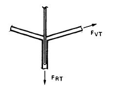
2. Vent Tape. From the geometric design of the parachute vent (Figure 7-11). the force in the vent tape, Failed to parse (SVG (MathML can be enabled via browser plugin): Invalid response ("Math extension cannot connect to Restbase.") from server "https://wikimedia.org/api/rest_v1/":): {\displaystyle F_VT} , is calculated
Failed to parse (SVG (MathML can be enabled via browser plugin): Invalid response ("Math extension cannot connect to Restbase.") from server "https://wikimedia.org/api/rest_v1/":): {\displaystyle F_{VT} = \frac{F_{RT}}{N_ {SL}\ 2\ sin[\frac{360}{N_{SL}}]}DF}
Failed to parse (SVG (MathML can be enabled via browser plugin): Invalid response ("Math extension cannot connect to Restbase.") from server "https://wikimedia.org/api/rest_v1/":): {\displaystyle = \frac{9255}{64(2\ sin\frac{360}{64})}1.85=1360\ lb}
A 1-inch-wide, 4000-pound webbing (MIL-W-5625) or 7/8-inch-wide, 3100-pound webbing (MIL-W-5625) is selected.
3. Vent Lines. The strength of the vent line- should be equal to or greater than 60% of the strength of the radials.
7.3.8.7 Design of Radials
The following four types of radial designs are in use:
1. Radial seams with suspension lines running in channels over the canopy and attached at the vent and the skirt as on the canopy of the C-9 personnel parachute.
2. Suspension lines running on top of the radials over the canopy and sewn at full length to the canopy as on many heavy-duty ribbon parachutes.
3. Radial tapes sewn on top of or inside the radial seams, and suspension lines attached to the radial tapes by sewing or by skirt loops (NB-7 and T-10 canopies).
4. Radial ribbons on ribbon parachutes designed to take the total radial load with suspension lines sewn onto d e radials or connected by a skirt loop.
The following are some comments on the design of radials:
1. Making the strength of the radials equal to 80% of the strength of the suspension lines has been satisfactory on thousands of ribbon parachutes.
2. When tapes or suspension lines are sewn at full length to the radials, care must be taken that fullness in the radials ensures that the radial tapes or the suspension lines are the primary load carrying members. For an explanation of fullness, see section 6.6.4.
3. Uniform material distribution is of utmost importance when sewn tapes or lines are used for radial reinforcement.
For the radial design of the main parachute, we use a tape with 80% strength of the suspension line (Failed to parse (SVG (MathML can be enabled via browser plugin): Invalid response ("Math extension cannot connect to Restbase.") from server "https://wikimedia.org/api/rest_v1/":): {\displaystyle 0.8\cdot 300\ lb =240\ lb} ) sewn on top of the radial seam. A 250-pound strength, Failed to parse (SVG (MathML can be enabled via browser plugin): Invalid response ("Math extension cannot connect to Restbase.") from server "https://wikimedia.org/api/rest_v1/":): {\displaystyle \frac{_1}{_2}} -inch-wide tape is selected in accordance with MIL-T -5038, Type III. Tape and radial seams are marked every 24 inches for proper material distribution.
7.3.8.8 Check for Proper Gore Fullness
When the first parachute of a new design has been completed in the manufacturing shop, a gore fullness check in accordance with Figure 7-12 should be conducted. A slight amount of slack should be noticeable in the canopy fabric in both directions when all four corners of a gore are pulled radially outward. Slack indicates that the main loads are carried by the radials and reinforcing tapes and not by the canopy fabric. Stress folds in the canopy indicate faults in the design or manufacture of the parachute.

7.3.9 Canopy Gore Shape
A full-extended-skirt parachute is selected that has a conical top with a 25-degree cone angle; a nominal diameter, Do, of 72.7 feet; and 64 gores.
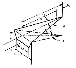
Based on the definitions in Figure 7-13. the canopy gore dimensions are
Failed to parse (SVG (MathML can be enabled via browser plugin): Invalid response ("Math extension cannot connect to Restbase.") from server "https://wikimedia.org/api/rest_v1/":): {\displaystyle Base\ gore\ angle\ \gamma = \frac{360\ deg}{N_{SL}}=\frac{360}{64}=5.625\ deg}
Failed to parse (SVG (MathML can be enabled via browser plugin): Invalid response ("Math extension cannot connect to Restbase.") from server "https://wikimedia.org/api/rest_v1/":): {\displaystyle Cone\ angle\ \mu=25\deg}
Failed to parse (SVG (MathML can be enabled via browser plugin): Invalid response ("Math extension cannot connect to Restbase.") from server "https://wikimedia.org/api/rest_v1/":): {\displaystyle Gore\ angle\ \beta=sin^{-1}[cos\ \mu[sin\frac{180}{N_{SL}}]]}
Failed to parse (SVG (MathML can be enabled via browser plugin): Invalid response ("Math extension cannot connect to Restbase.") from server "https://wikimedia.org/api/rest_v1/":): {\displaystyle \beta = sin^{-1}[0.9063(sin\ 2.8125\ deg)]}
Failed to parse (SVG (MathML can be enabled via browser plugin): Invalid response ("Math extension cannot connect to Restbase.") from server "https://wikimedia.org/api/rest_v1/":): {\displaystyle \beta=\ sin^{-1}(0.9063)(0.0491)=2\ sin^{-1}=0.0447}
Failed to parse (SVG (MathML can be enabled via browser plugin): Invalid response ("Math extension cannot connect to Restbase.") from server "https://wikimedia.org/api/rest_v1/":): {\displaystyle \beta= 5.1\ deg}
Failed to parse (SVG (MathML can be enabled via browser plugin): Invalid response ("Math extension cannot connect to Restbase.") from server "https://wikimedia.org/api/rest_v1/":): {\displaystyle Canopy\ surface\ area\ S_o = 4160\ ft^2 (see\ section\ 7.3.3)}
Failed to parse (SVG (MathML can be enabled via browser plugin): Invalid response ("Math extension cannot connect to Restbase.") from server "https://wikimedia.org/api/rest_v1/":): {\displaystyle Gore\ height\ h_1 = \sqrt{\frac{(0.653\ S_o)(144)cot\ \gamma/2}{N_{SL}\cdot cos\mu}}}
Failed to parse (SVG (MathML can be enabled via browser plugin): Invalid response ("Math extension cannot connect to Restbase.") from server "https://wikimedia.org/api/rest_v1/":): {\displaystyle h_1 = \sqrt{\frac{(0.653)(4160)(144)(20.34)}{(64)(0.9063)}}}
Failed to parse (SVG (MathML can be enabled via browser plugin): Invalid response ("Math extension cannot connect to Restbase.") from server "https://wikimedia.org/api/rest_v1/":): {\displaystyle h_1 = 370.3\ in.}
Failed to parse (SVG (MathML can be enabled via browser plugin): Invalid response ("Math extension cannot connect to Restbase.") from server "https://wikimedia.org/api/rest_v1/":): {\displaystyle h_2=0.286h_1=0.286(372.73)=105.9\ in.}
Failed to parse (SVG (MathML can be enabled via browser plugin): Invalid response ("Math extension cannot connect to Restbase.") from server "https://wikimedia.org/api/rest_v1/":): {\displaystyle e_1=2h_1(tan\ \beta / 2)=(2)(372.73)(0.0445)=32.96\ in.}
Failed to parse (SVG (MathML can be enabled via browser plugin): Invalid response ("Math extension cannot connect to Restbase.") from server "https://wikimedia.org/api/rest_v1/":): {\displaystyle h_s=h_1 + h_2=370.3+105.9 =476.2\ in.}
7.3.9.1 Vent Area
A vent area, Failed to parse (SVG (MathML can be enabled via browser plugin): Invalid response ("Math extension cannot connect to Restbase.") from server "https://wikimedia.org/api/rest_v1/":): {\displaystyle S_V} , is selected that is equal to 0.25% of the total canopy surface area, Failed to parse (SVG (MathML can be enabled via browser plugin): Invalid response ("Math extension cannot connect to Restbase.") from server "https://wikimedia.org/api/rest_v1/":): {\displaystyle S_o} ; therefore,
Failed to parse (SVG (MathML can be enabled via browser plugin): Invalid response ("Math extension cannot connect to Restbase.") from server "https://wikimedia.org/api/rest_v1/":): {\displaystyle S_V=(0.0025)S_o=0.0025(4160)=10.4\ ft^2} and the
vent diameter, Failed to parse (SVG (MathML can be enabled via browser plugin): Invalid response ("Math extension cannot connect to Restbase.") from server "https://wikimedia.org/api/rest_v1/":): {\displaystyle D_V=1.1284\sqrt{S_V}=1.1284\sqrt{10.4}=3.64\ ft}
This is a large vent opening for a reefed parachute. Several criteria may be used to determine the size of the canopy vent as follows:
1. Unreefed parachutes with vents up to 1% of the canopy surface area, Failed to parse (SVG (MathML can be enabled via browser plugin): Invalid response ("Math extension cannot connect to Restbase.") from server "https://wikimedia.org/api/rest_v1/":): {\displaystyle S_o} , have been operated successfully.
2. Reefed parachutes require a vent diameter, Failed to parse (SVG (MathML can be enabled via browser plugin): Invalid response ("Math extension cannot connect to Restbase.") from server "https://wikimedia.org/api/rest_v1/":): {\displaystyle D_V} , smaller than the reefing line circle, diameter Failed to parse (SVG (MathML can be enabled via browser plugin): Invalid response ("Math extension cannot connect to Restbase.") from server "https://wikimedia.org/api/rest_v1/":): {\displaystyle D_R} , of the parachute; Failed to parse (SVG (MathML can be enabled via browser plugin): Invalid response ("Math extension cannot connect to Restbase.") from server "https://wikimedia.org/api/rest_v1/":): {\displaystyle D_V} is smaller than Failed to parse (SVG (MathML can be enabled via browser plugin): Invalid response ("Math extension cannot connect to Restbase.") from server "https://wikimedia.org/api/rest_v1/":): {\displaystyle D_R} (see section 5.6, Figure 5-66).
3. The radials at the vent should not overlap. A 1-inch free space between radials is desirable (see Figure 7-14).
7.3.9.2 Vent Diameter
A vent construction is selected with a 1-inch free space between 1-inch-wide radials; this results in a vent circumference of 64 + 63 = 127 in. and a vent diameter of
Failed to parse (SVG (MathML can be enabled via browser plugin): Invalid response ("Math extension cannot connect to Restbase.") from server "https://wikimedia.org/api/rest_v1/":): {\displaystyle D_V = \frac{127}{\pi}=40.43\ in.}
A 3-foot vent diameter is selected. The radius is 18 inches, and vent height, Failed to parse (SVG (MathML can be enabled via browser plugin): Invalid response ("Math extension cannot connect to Restbase.") from server "https://wikimedia.org/api/rest_v1/":): {\displaystyle h_v} , is calculated
Failed to parse (SVG (MathML can be enabled via browser plugin): Invalid response ("Math extension cannot connect to Restbase.") from server "https://wikimedia.org/api/rest_v1/":): {\displaystyle h_V=r(cos\ \gamma/2);gore\ half\ angle\ \gamma/2=2.55\ deg}
Failed to parse (SVG (MathML can be enabled via browser plugin): Invalid response ("Math extension cannot connect to Restbase.") from server "https://wikimedia.org/api/rest_v1/":): {\displaystyle h_V=18(0.999)=17.98\ in.}
Manufactured gore height, Failed to parse (SVG (MathML can be enabled via browser plugin): Invalid response ("Math extension cannot connect to Restbase.") from server "https://wikimedia.org/api/rest_v1/":): {\displaystyle h_g} , is
Failed to parse (SVG (MathML can be enabled via browser plugin): Invalid response ("Math extension cannot connect to Restbase.") from server "https://wikimedia.org/api/rest_v1/":): {\displaystyle h_g = h_1 - h_V =370.3 - 17.98 = 352.32 in.}
Vent gore width, Failed to parse (SVG (MathML can be enabled via browser plugin): Invalid response ("Math extension cannot connect to Restbase.") from server "https://wikimedia.org/api/rest_v1/":): {\displaystyle e_V} ,
Failed to parse (SVG (MathML can be enabled via browser plugin): Invalid response ("Math extension cannot connect to Restbase.") from server "https://wikimedia.org/api/rest_v1/":): {\displaystyle e_V=2h_V\ tan\beta/2=2(17.98)(0.0445)=1.6\ in.}
Stress in the canopy gore area can be relieved by making the gore at the vent 10% wider than the calculated gore dimension, Failed to parse (SVG (MathML can be enabled via browser plugin): Invalid response ("Math extension cannot connect to Restbase.") from server "https://wikimedia.org/api/rest_v1/":): {\displaystyle e_V}
. Therefore, Failed to parse (SVG (MathML can be enabled via browser plugin): Invalid response ("Math extension cannot connect to Restbase.") from server "https://wikimedia.org/api/rest_v1/":): {\displaystyle e_V^*=1.1 \cdot e_V=1.1(1.6)=1.76\ inches. }
The
vent tape is sewn to the vent at the original Failed to parse (SVG (MathML can be enabled via browser plugin): Invalid response ("Math extension cannot connect to Restbase.") from server "https://wikimedia.org/api/rest_v1/":): {\displaystyle e_V} dimension, thereby gathering the vent 10% and creating a stress-relieving arcing in the gore fabric next to the vent. See Figure 7-15 for an example of final gore dimensions.
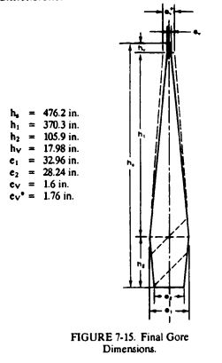
7.3.10 Pocket Bands
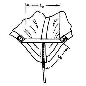
The pocket bands used on every gore make canopy inflation more uniform and eliminates long and short filling times. A narrow tape is used as the pocket band, which will not affect the average length of the canopy filling time. Data on the dimensioning of pocket bands are given in section 6.4. As shown in Figure 7-16, the pocket band dimensions are
Failed to parse (SVG (MathML can be enabled via browser plugin): Invalid response ("Math extension cannot connect to Restbase.") from server "https://wikimedia.org/api/rest_v1/":): {\displaystyle e_S=e_2=28.24\ in. }
Failed to parse (SVG (MathML can be enabled via browser plugin): Invalid response ("Math extension cannot connect to Restbase.") from server "https://wikimedia.org/api/rest_v1/":): {\displaystyle L_b=0.14e_s=0.14 \cdot 28.24=3.95\ in. }
Failed to parse (SVG (MathML can be enabled via browser plugin): Invalid response ("Math extension cannot connect to Restbase.") from server "https://wikimedia.org/api/rest_v1/":): {\displaystyle L_a= 0.238e_S=0.238\cdot 28.24=6.7\ in. }
A 5/8-inch-wide tape, MIL-T-8363, Type I, is selected as pocket band material.
Important Note: Pocket band length, Failed to parse (SVG (MathML can be enabled via browser plugin): Invalid response ("Math extension cannot connect to Restbase.") from server "https://wikimedia.org/api/rest_v1/":): {\displaystyle L_a } , must be long enough to permit the full inflation of the parachute canopy.Failed to parse (SVG (MathML can be enabled via browser plugin): Invalid response ("Math extension cannot connect to Restbase.") from server "https://wikimedia.org/api/rest_v1/":): {\displaystyle D_R}
7.3.11 Parachute Reefing
7.3.11.1 Length of Parachute Reefing Line
The drag area of a single reefed main parachute was calculated as Failed to parse (SVG (MathML can be enabled via browser plugin): Invalid response ("Math extension cannot connect to Restbase.") from server "https://wikimedia.org/api/rest_v1/":): {\displaystyle (C_DS)_R= 82.37\ square\ feet} (see section 7.3.7.4). This area results in the following reefing ratio:
Failed to parse (SVG (MathML can be enabled via browser plugin): Invalid response ("Math extension cannot connect to Restbase.") from server "https://wikimedia.org/api/rest_v1/":): {\displaystyle \epsilon=\frac{(C_DS)_R}{(C_DS)_o}=\frac{82.37}{3744}=0.022=2.2%\ of\ S_o}
Reefing by the skirt-reefing method is selected (see section 5.6, Figure 5-66 and section 6.5).
From Figure 5-72, we obtain for an extended-skirt parachute with a reefing ratio Failed to parse (SVG (MathML can be enabled via browser plugin): Invalid response ("Math extension cannot connect to Restbase.") from server "https://wikimedia.org/api/rest_v1/":): {\displaystyle \epsilon = 0.22} , a reefing-line ratio:
Failed to parse (SVG (MathML can be enabled via browser plugin): Invalid response ("Math extension cannot connect to Restbase.") from server "https://wikimedia.org/api/rest_v1/":): {\displaystyle \tau=D_R/D_o=0.07}
and the diameter of the reefing-line circle, Failed to parse (SVG (MathML can be enabled via browser plugin): Invalid response ("Math extension cannot connect to Restbase.") from server "https://wikimedia.org/api/rest_v1/":): {\displaystyle D_R} :
Failed to parse (SVG (MathML can be enabled via browser plugin): Invalid response ("Math extension cannot connect to Restbase.") from server "https://wikimedia.org/api/rest_v1/":): {\displaystyle D_R=(0.07)D_o=0.07\cdot 72.7\ ft=5.09\ ft}
and the installed length of the reefing line, Failed to parse (SVG (MathML can be enabled via browser plugin): Invalid response ("Math extension cannot connect to Restbase.") from server "https://wikimedia.org/api/rest_v1/":): {\displaystyle L_RL} :
Failed to parse (SVG (MathML can be enabled via browser plugin): Invalid response ("Math extension cannot connect to Restbase.") from server "https://wikimedia.org/api/rest_v1/":): {\displaystyle L_{RL}=D_R\ \pi=5.09\pi=15.99\ ft=191.88\ in. }
The diameter of the reefing line circle, Failed to parse (SVG (MathML can be enabled via browser plugin): Invalid response ("Math extension cannot connect to Restbase.") from server "https://wikimedia.org/api/rest_v1/":): {\displaystyle D_R} , is larger than the 3.64-foot vent diameter of the canopy, Failed to parse (SVG (MathML can be enabled via browser plugin): Invalid response ("Math extension cannot connect to Restbase.") from server "https://wikimedia.org/api/rest_v1/":): {\displaystyle D_V} . This difference in diameters is an important design requirement (see section 7.3.9).
7.3.11.2 Strength of the Reefing Line
The force in the reefing line is determined according to information in section 5.6.8. Test items 22 and 23 in Figure 5-76 closely resemble the main parachute used here. A reefing-line-force-to-reefed-parachute-force ratio of 2.5% is selected for this assembly. Therefore, the force in the reefing line is
Failed to parse (SVG (MathML can be enabled via browser plugin): Invalid response ("Math extension cannot connect to Restbase.") from server "https://wikimedia.org/api/rest_v1/":): {\displaystyle (0.025)F_R=0.025(9255\ lb)=231.4\ lb}
The design factor, Failed to parse (SVG (MathML can be enabled via browser plugin): Invalid response ("Math extension cannot connect to Restbase.") from server "https://wikimedia.org/api/rest_v1/":): {\displaystyle D_F} , for the reefing system was determined in section 7.3.8, Table 7-4, to be 2.74.
Required reefing-line strength, Failed to parse (SVG (MathML can be enabled via browser plugin): Invalid response ("Math extension cannot connect to Restbase.") from server "https://wikimedia.org/api/rest_v1/":): {\displaystyle F_{RL_{ULTIMATE}}} , is
Failed to parse (SVG (MathML can be enabled via browser plugin): Invalid response ("Math extension cannot connect to Restbase.") from server "https://wikimedia.org/api/rest_v1/":): {\displaystyle F_{RL_{ULTIMATE}}=DF\cdot F_{RL}=2.74\cdot 231.4\ lb = 634\ lb }
A coreless braided nylon line, MIL-C-7565, Type III, with a tensile strength of 750 pounds, is selected as reefing line.
Section 6.5 discusses reefing system design and installation details.
7.4 HIGH-SPEED DROGUE CHUTE ASSEMBLY
7.4.1 Requirements
The following operational requirements govern the design of the first-stage drogue chute:
1. The drone must be recoverable from any conceivable flight condition during the engineering test phase.
2. An out-of-control drone or a drone that loses radio contact with the controller must be prevented from flying off the range. Recovery is initiated by an independent range signal. This type of recovery requires a high-speed deceleration parachute that can be deployed and operated when the drone is moving at maximum speed, or is in a spin, or during any other abnormal flight condition.
This type of recovery established the following requirements for the type and size of the drogue chute:
1. The drogue chute must have reliable operation in the velocity range from 200 knots at sea level to Mach 1.5 at 50,000 feet.
2. Stability must be better than Failed to parse (SVG (MathML can be enabled via browser plugin): Invalid response ("Math extension cannot connect to Restbase.") from server "https://wikimedia.org/api/rest_v1/":): {\displaystyle \pm} 3 degrees.
3. Minimum weight and volume are mandatory.
4. The drogue chute must be able to decelerate the drone to the permissible opening speed of the main parachute assemblies.
5. The drogue chute must be suitable for the operational environment.
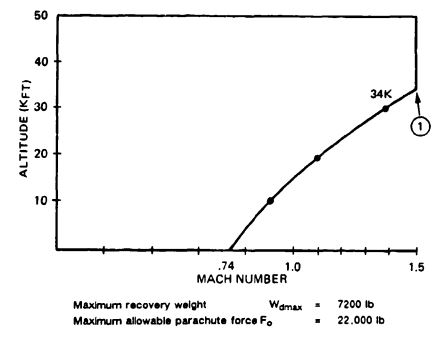
Figure 7-17 shows the altitude-velocity flight envelope of the drone.
7.4.2 Drogue Chute Selection
Tables 5-1 through Table 5-5 in Chapter 5 list commonly used parachute types. Table 7-6 evaluates possible drogue chute candidates. Of the parachute candidates, only the conical ribbon and the hemisflo ribbon have been used successfully for similar applications.
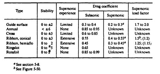
A 25-degree conical ribbon parachute is selected for this application. The conical ribbon parachute meets all requirements and has a higher subsonic drag coefficient than the equally suited hemisflo parachute. The subsonic drag coefficient determined the parachute size and its associated weight and volume. Numerous conical ribbon parachutes have been used successfully at this speed and diameter range.
Based on section 5.8, Figure 5-93, we obtain the following drag coefficients versus Mach number data:
| Mach number | 1.5 | 1.3 | 1.1 | 1.0 | 0.8 |
|---|---|---|---|---|---|
| Failed to parse (SVG (MathML can be enabled via browser plugin): Invalid response ("Math extension cannot connect to Restbase.") from server "https://wikimedia.org/api/rest_v1/":): {\displaystyle C_{D{_o}}} | 0.42 | 0.5 | 0.52 | 0.55 | 0.55 |
These Failed to parse (SVG (MathML can be enabled via browser plugin): Invalid response ("Math extension cannot connect to Restbase.") from server "https://wikimedia.org/api/rest_v1/":): {\displaystyle C_{D_{o}}} coefficients do not take into account a loss caused by forebody wake.
7.4.3 Required Drogue Chute Diameter
The size of the fully open drogue chute is determined by the requirement that it must decelerate the 7200-pound drone to the allowable opening speed of the main parachute, which is governed by the requirement that the opening force of the two main parachutes must stay within the 9350-pound-per-chute limit established for the 200-knot opening speed of the 4800-pound drone.
A preliminary calculation shows that a terminal velocity of about 175 KEAS is required to limit the opening load of the reefed main parachutes to 9350 pounds. A 13 to 14-foot-diameter drogue chute is needed to meet this requirement.
To reach 175 KEAS at main parachute line stretch, the drogue chute will be disconnected by an aneroid sensor at about 7000 feet mean sea level (MSL) while descending vertically from high altitude. The drone will free-fall for 0.8 second until main parachute line stretch occurs; the free-fall causes a 10-knot increase in velocity. In addition, the changing density, Failed to parse (SVG (MathML can be enabled via browser plugin): Invalid response ("Math extension cannot connect to Restbase.") from server "https://wikimedia.org/api/rest_v1/":): {\displaystyle \rho} , results in about 5 KEAS Failed to parse (SVG (MathML can be enabled via browser plugin): Invalid response ("Math extension cannot connect to Restbase.") from server "https://wikimedia.org/api/rest_v1/":): {\displaystyle \Delta V} compared to equilibrium velocity. We therefore design for a terminal velocity of 175 - (10 + 5) knots, or 160 KEAS.
Dynamic pressure, q, at 160 KEAS = Failed to parse (SVG (MathML can be enabled via browser plugin): Invalid response ("Math extension cannot connect to Restbase.") from server "https://wikimedia.org/api/rest_v1/":): {\displaystyle \frac{160^2}{295}=86.78\ lb/ft^2}
Required drogue chute drag area, (CDS)p = 7 lbt2 2 82.95 lb/ft2
q 86.8 ib/ft =
Drogue chute canopy area, Failed to parse (SVG (MathML can be enabled via browser plugin): Invalid response ("Math extension cannot connect to Restbase.") from server "https://wikimedia.org/api/rest_v1/":): {\displaystyle (C_DS)_p=\frac{W_{TO}}{q}=\frac{7200\ lb}{86.8\ lb/ft^2}=82.95\ lb/ft^2}
Nominal diameter, Failed to parse (SVG (MathML can be enabled via browser plugin): Invalid response ("Math extension cannot connect to Restbase.") from server "https://wikimedia.org/api/rest_v1/":): {\displaystyle D_o=1.128\sqrt{S_o}=1.128\sqrt{150.9}=13.85\ ft}
and the inflated diameter Failed to parse (SVG (MathML can be enabled via browser plugin): Invalid response ("Math extension cannot connect to Restbase.") from server "https://wikimedia.org/api/rest_v1/":): {\displaystyle D_p=D_oC=13.85\cdot 0.65=9\ ft. }
The drag coefficient will be reduced because of the forebody wake and will increase if suspension lines are longer than Failed to parse (SVG (MathML can be enabled via browser plugin): Invalid response ("Math extension cannot connect to Restbase.") from server "https://wikimedia.org/api/rest_v1/":): {\displaystyle L_e/D_o=1.0.}
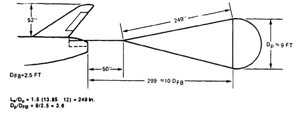
Suspension lines equal in length to 1.5 Do, are selected, causing an 8.5% Failed to parse (SVG (MathML can be enabled via browser plugin): Invalid response ("Math extension cannot connect to Restbase.") from server "https://wikimedia.org/api/rest_v1/":): {\displaystyle C_{D_{o}}}
gain, (see Figure 5-20). The loss in drag caused by forebody wake is determined from Figure 5-21. The ratio of inflated parachute diameter, Failed to parse (SVG (MathML can be enabled via browser plugin): Invalid response ("Math extension cannot connect to Restbase.") from server "https://wikimedia.org/api/rest_v1/":): {\displaystyle D_p}
, to forebody diameter, Failed to parse (SVG (MathML can be enabled via browser plugin): Invalid response ("Math extension cannot connect to Restbase.") from server "https://wikimedia.org/api/rest_v1/":): {\displaystyle D_{FB}}
, is 3.6, and the ratio of the distance between the leading edge of the inflated parachute and the aft end of the drone is 300/30 in. = 10 as shown in Figure 7-18. The gain in drag caused by the longer suspension lines and the 5% loss in drag caused by forebody wake (Figure 5-21) result in a final drag coefficient, Failed to parse (SVG (MathML can be enabled via browser plugin): Invalid response ("Math extension cannot connect to Restbase.") from server "https://wikimedia.org/api/rest_v1/":): {\displaystyle C_{D_o}}
, for the drogue chute of
Failed to parse (SVG (MathML can be enabled via browser plugin): Invalid response ("Math extension cannot connect to Restbase.") from server "https://wikimedia.org/api/rest_v1/":): {\displaystyle {\displaystyle C_{D_{o}}}=0.55\cdot 1.085 \cdot 0.95 = 0.57}
and a corrected drogue chute diameter
Failed to parse (SVG (MathML can be enabled via browser plugin): Invalid response ("Math extension cannot connect to Restbase.") from server "https://wikimedia.org/api/rest_v1/":): {\displaystyle D_o = 13.61\ ft}
7.4.4 Computer Analysis of Drogue Chute Performance
At this point, a computer program should be established to determine the following performance conditions:
1. Balance reefed and disreef parachute forces and filling times. Start at Mach 1.5 at 34,000 feet (see point (1) on Figure 7-17). Check final selection for a 10,000-foot-altitude condition.
2. Determine required opening altitude for high-speed, low-altitude deployment. This requires trajectory runs with both the drogue and main parachutes.
3. Determine maximum horizontal range, including prevailing wind conditions.
4. Verify that the selected main parachute opening speed of 175 KEAS is reached for all important flight conditions and that, for an opening velocity of 175 KEAS, the main parachute forces stay within the allowable force limit of 9255 pounds.
5. Include opening of the air bags with a 6.0-second inflation time in some of the trajectories. Inflation starts after main parachute opening.
The prime contractor should point out any special flight conditions that may require parachute recovery. The prime contractor will probably also perform recovery computer runs to determine for which flight conditions and from what altitudes recovery can be accomplished.
7.4.5 Flight Emergency Recovery Conditions
Certain flight conditions other than recovery command from the flight controller or the range safety officer may result in automatic on-board recovery command. These conditions include
1. Loss of RF link.
2. Loss of engine power (glide on internal power).
3. High accelerations in x, y, and z caused by out-of-control flight conditions or in-flight-afflicted damage on target drones.
7.4.6 Drogue Chute Opening Forces
Parachute opening forces should be obtained from the computer program. However, a hand calculation is required for defining the force range before setting up the computer program. Furthermore, canopy filling times and force coefficient, Failed to parse (SVG (MathML can be enabled via browser plugin): Invalid response ("Math extension cannot connect to Restbase.") from server "https://wikimedia.org/api/rest_v1/":): {\displaystyle C_x} , must be determined before computer runs (see section 5.4).
Determining the drogue chute opening forces with the W/CDS method is normally sufficiently accurate for high-canopy-loading drogue chutes. If no computer backup is available, the Pflanz method (see section 5.4.6) will provide good force data.
7.4.6.1 Drogue Chute Reefed Opening Forces
When the Failed to parse (SVG (MathML can be enabled via browser plugin): Invalid response ("Math extension cannot connect to Restbase.") from server "https://wikimedia.org/api/rest_v1/":): {\displaystyle W/C_DS} method is used, the reefed opening force, Failed to parse (SVG (MathML can be enabled via browser plugin): Invalid response ("Math extension cannot connect to Restbase.") from server "https://wikimedia.org/api/rest_v1/":): {\displaystyle F_R} , is calculated to
Failed to parse (SVG (MathML can be enabled via browser plugin): Invalid response ("Math extension cannot connect to Restbase.") from server "https://wikimedia.org/api/rest_v1/":): {\displaystyle F_R=(C_DS)_R\cdot q \cdot C_x \cdot X_1}
and the maximum allowable drogue chute drag area with a 22,000-force limit is calculated to
Failed to parse (SVG (MathML can be enabled via browser plugin): Invalid response ("Math extension cannot connect to Restbase.") from server "https://wikimedia.org/api/rest_v1/":): {\displaystyle (C_DS)R=\frac{F_R}{q\cdot C_x \cdot X_1}}
where
Failed to parse (SVG (MathML can be enabled via browser plugin): Invalid response ("Math extension cannot connect to Restbase.") from server "https://wikimedia.org/api/rest_v1/":): {\displaystyle F_R} , the maximum allowable force, is 22,000 lb
q, the maximum dynamic pressure, is Failed to parse (SVG (MathML can be enabled via browser plugin): Invalid response ("Math extension cannot connect to Restbase.") from server "https://wikimedia.org/api/rest_v1/":): {\displaystyle 813.9 lb/ft^2}
For supersonic application, Figure 5-50 in section 5.4 shows Failed to parse (SVG (MathML can be enabled via browser plugin): Invalid response ("Math extension cannot connect to Restbase.") from server "https://wikimedia.org/api/rest_v1/":): {\displaystyle C_K=C_x\cdot X_1} for the supersonic deployment of conical ribbon parachutes. Most applicable are the data for the Mercury and the Cook conical ribbon parachutes, which were deployed at velocities up to Mach 1.6. Failed to parse (SVG (MathML can be enabled via browser plugin): Invalid response ("Math extension cannot connect to Restbase.") from server "https://wikimedia.org/api/rest_v1/":): {\displaystyle C_K} factors of 1.3 to 1.75 have been measured in supersonic deployment of conical ribbon parachutes. Forebody wake and poor deployment greatly affect the force coefficient. Mortar deployment often produces bag strip-off before canopy stretch, causing premature partial canopy inflation and a high Failed to parse (SVG (MathML can be enabled via browser plugin): Invalid response ("Math extension cannot connect to Restbase.") from server "https://wikimedia.org/api/rest_v1/":): {\displaystyle X_1} factor. Rocket extraction or drogue gun/pilot chute deployment, both resulting in canopy stretch before skirt inflation, generally avoid this problem. A force coefficient Failed to parse (SVG (MathML can be enabled via browser plugin): Invalid response ("Math extension cannot connect to Restbase.") from server "https://wikimedia.org/api/rest_v1/":): {\displaystyle C_x=1.25} is selected.
Failed to parse (SVG (MathML can be enabled via browser plugin): Invalid response ("Math extension cannot connect to Restbase.") from server "https://wikimedia.org/api/rest_v1/":): {\displaystyle X_1} is a function of Failed to parse (SVG (MathML can be enabled via browser plugin): Invalid response ("Math extension cannot connect to Restbase.") from server "https://wikimedia.org/api/rest_v1/":): {\displaystyle \frac{W}{(C_DS)_R}} that is unknown at this time, but (based on experience) is estimated to be 0.95 and corrected afterward:
Failed to parse (SVG (MathML can be enabled via browser plugin): Invalid response ("Math extension cannot connect to Restbase.") from server "https://wikimedia.org/api/rest_v1/":): {\displaystyle (C_DS)_R=\frac{22,000\ lb}{(813.9\ lb.ft^2)(1.25)(0.95)}=22.76\ ft^2}
The canopy loading of the reefed drogue chute is
Failed to parse (SVG (MathML can be enabled via browser plugin): Invalid response ("Math extension cannot connect to Restbase.") from server "https://wikimedia.org/api/rest_v1/":): {\displaystyle \frac{W_{d\ max}}{(C_DS)_R}=\frac{7200}{22.76}=316.3\ lb/ft^2}
for this Failed to parse (SVG (MathML can be enabled via browser plugin): Invalid response ("Math extension cannot connect to Restbase.") from server "https://wikimedia.org/api/rest_v1/":): {\displaystyle \frac{W}{(C_DS)_R}} . Figure 5-48 shows Failed to parse (SVG (MathML can be enabled via browser plugin): Invalid response ("Math extension cannot connect to Restbase.") from server "https://wikimedia.org/api/rest_v1/":): {\displaystyle X_1} = 1.0; the corrected reefed-drogue-chute drag area is calculated
Failed to parse (SVG (MathML can be enabled via browser plugin): Invalid response ("Math extension cannot connect to Restbase.") from server "https://wikimedia.org/api/rest_v1/":): {\displaystyle (C_DS)_R=\frac{22,000\ lb}{(813.9\ lb.ft^2)(1.25)(1.0)}=21.62\ ft^2}
The required reefing-line length for obtaining this drag area can be determined from Figure 5-73, section 5.6.6, using the method of section 7.3.11.
7.4.6.2 Drogue Chute Disreef Opening Force
An important factor to determine is reefing time. A long time is required to reach close to terminal velocity before disreef. A practical approach, based on experience, is to select the 1.1-times-terminal-velocity point for disreef. If this time is too long, then a shorter reefing time is required, resulting in a higher disreef velocity and forces.
The terminal velocity of the reefed parachute is
Failed to parse (SVG (MathML can be enabled via browser plugin): Invalid response ("Math extension cannot connect to Restbase.") from server "https://wikimedia.org/api/rest_v1/":): {\displaystyle q_{terminal}=\frac{W_{d\ max}}{(C_DS)_R+(C_DS)_{drone}}=\frac{7200\ lb}{21.62+0.115\cdot 75\ ft^2}=\frac{7200}{30.26}}
Failed to parse (SVG (MathML can be enabled via browser plugin): Invalid response ("Math extension cannot connect to Restbase.") from server "https://wikimedia.org/api/rest_v1/":): {\displaystyle q_{terminal}=237.9\ lb/ft^2=265\ KEAS}
Disreef occurs at Failed to parse (SVG (MathML can be enabled via browser plugin): Invalid response ("Math extension cannot connect to Restbase.") from server "https://wikimedia.org/api/rest_v1/":): {\displaystyle 1.1(q_{terminal})=1.1(237.9)=261.7\ lb/ft^2}
The disreef force is
Failed to parse (SVG (MathML can be enabled via browser plugin): Invalid response ("Math extension cannot connect to Restbase.") from server "https://wikimedia.org/api/rest_v1/":): {\displaystyle F_o=(C_DS)_p\cdot q \cdot C_x \cdot X_1}
Failed to parse (SVG (MathML can be enabled via browser plugin): Invalid response ("Math extension cannot connect to Restbase.") from server "https://wikimedia.org/api/rest_v1/":): {\displaystyle C_x} for disreef is 1.10
Failed to parse (SVG (MathML can be enabled via browser plugin): Invalid response ("Math extension cannot connect to Restbase.") from server "https://wikimedia.org/api/rest_v1/":): {\displaystyle X_1=f[\frac{W}{(C_DS)_D}]}
Failed to parse (SVG (MathML can be enabled via browser plugin): Invalid response ("Math extension cannot connect to Restbase.") from server "https://wikimedia.org/api/rest_v1/":): {\displaystyle \frac{W}{(C_DS)_D}=\frac{7200}{82.95}=86.8\ lb/ft^2} and Failed to parse (SVG (MathML can be enabled via browser plugin): Invalid response ("Math extension cannot connect to Restbase.") from server "https://wikimedia.org/api/rest_v1/":): {\displaystyle X_1} from Figure 5-48 = 0.92
and disreef force, Fo, is calculated
Failed to parse (SVG (MathML can be enabled via browser plugin): Invalid response ("Math extension cannot connect to Restbase.") from server "https://wikimedia.org/api/rest_v1/":): {\displaystyle F_o=(C_DS)_D\cdot q \cdot C_x \cdot X_1 }
Failed to parse (SVG (MathML can be enabled via browser plugin): Invalid response ("Math extension cannot connect to Restbase.") from server "https://wikimedia.org/api/rest_v1/":): {\displaystyle F_o = (82.95)(251.7)(1.10)(0.92)=21,968\ lb}
Both forces Failed to parse (SVG (MathML can be enabled via browser plugin): Invalid response ("Math extension cannot connect to Restbase.") from server "https://wikimedia.org/api/rest_v1/":): {\displaystyle F_R} and Failed to parse (SVG (MathML can be enabled via browser plugin): Invalid response ("Math extension cannot connect to Restbase.") from server "https://wikimedia.org/api/rest_v1/":): {\displaystyle F_o} are close to the allowable force limit of 22,000 pounds. Because loads vary 5 to 10%, slight overloads may occur. However, the 7200-pound drone weight is the take-off weight. Off-range recovery and conceivable emergencies will occur at lighter drone weights, resulting in lower parachute forces.
7.4.7 Drogue Chute Stress Analysis and Design
Dimensioning of the various components of the parachute assembly involves three primary tasks (1) establishing design and safety factors, (2) determining the loads and stresses in the assembly components, and (3) dimensioning all assembly members. The methods used for these tasks are described in section 6.4.
7.4.7.1 Drogue Chute Safety, Load, Loss, and Design Factors
The method used is similar to the one developed in section 6.4. Table 7-7 shows safety, load, and loss factors in relation to design factor.
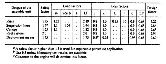
7.4.7.2 Number of Gores and Suspension-Line Strength
The drogue chute will be designed for a maximum force, Failed to parse (SVG (MathML can be enabled via browser plugin): Invalid response ("Math extension cannot connect to Restbase.") from server "https://wikimedia.org/api/rest_v1/":): {\displaystyle F_o} , of 22,000 pounds in the reefed and full-open stages. The suspension-line arrangement was selected in accordance with Table 7-8.
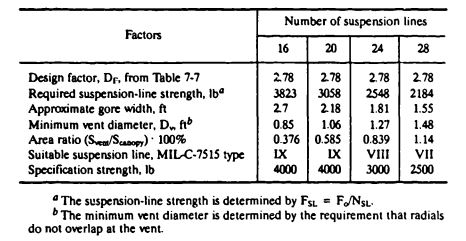
A canopy with 24 gores and 3000-pound-individual-strength suspension lines is selected primarily for gore width and vent diameter. The relatively large vent must be covered with wide vent lines held in place by proper connections.
The method described in section 6.4 is used for preliminary dimensioning of the horizontal ribbons. In this method, the expression Failed to parse (SVG (MathML can be enabled via browser plugin): Invalid response ("Math extension cannot connect to Restbase.") from server "https://wikimedia.org/api/rest_v1/":): {\displaystyle F_o/(C_DS)_P} is an indication of the pressure in the parachute canopy; the gore width, Failed to parse (SVG (MathML can be enabled via browser plugin): Invalid response ("Math extension cannot connect to Restbase.") from server "https://wikimedia.org/api/rest_v1/":): {\displaystyle e_S} , is an indication of the gore radius. A smaller gore width and resultant gore radius causes lower stress in the individual horizontal ribbons for a given internal pressure. Figure 6-41 shows boundary curves for the required horizontal ribbon strength. These data, based on analysis of many tested ribbon parachutes, were first presented in Reference 5.39 and subsequently updated by the author.
For the reefed parachute,
Failed to parse (SVG (MathML can be enabled via browser plugin): Invalid response ("Math extension cannot connect to Restbase.") from server "https://wikimedia.org/api/rest_v1/":): {\displaystyle F_R/(C_DS)_R=\frac{22,000\ lb}{21.62\ ft^2}=1017.6\ lb/ft^2}
The gore width of the reefed parachute is obtained from the following consideration. The reefed drag area is equivalent to the drag area of a parachute with the following nominal diameter (Failed to parse (SVG (MathML can be enabled via browser plugin): Invalid response ("Math extension cannot connect to Restbase.") from server "https://wikimedia.org/api/rest_v1/":): {\displaystyle D_{R_C}} ):
Failed to parse (SVG (MathML can be enabled via browser plugin): Invalid response ("Math extension cannot connect to Restbase.") from server "https://wikimedia.org/api/rest_v1/":): {\displaystyle S_{o_{reefed}}=\frac{(C_DS)_R}{C_{D_o}}=\frac{21.62\ ft^2}{0.55}=39.31\ ft^2}
The equivalent nominal diameter for the reefed parachute is
Failed to parse (SVG (MathML can be enabled via browser plugin): Invalid response ("Math extension cannot connect to Restbase.") from server "https://wikimedia.org/api/rest_v1/":): {\displaystyle D_{R{_o}}=1.128\sqrt{S_o}=1.128\sqrt{39.31}=7.07\ ft }
and the gore width is
Failed to parse (SVG (MathML can be enabled via browser plugin): Invalid response ("Math extension cannot connect to Restbase.") from server "https://wikimedia.org/api/rest_v1/":): {\displaystyle e_{r_s}=\frac{D_{R_o}\pi}{N_{SL}}=\frac{(7.07)\pi}{24}=0.93\ ft }
For an Failed to parse (SVG (MathML can be enabled via browser plugin): Invalid response ("Math extension cannot connect to Restbase.") from server "https://wikimedia.org/api/rest_v1/":): {\displaystyle \frac{F_{R_o}}{(C_DS)_P} } of Failed to parse (SVG (MathML can be enabled via browser plugin): Invalid response ("Math extension cannot connect to Restbase.") from server "https://wikimedia.org/api/rest_v1/":): {\displaystyle 1017.6\ lb/ft^2 } and gore width of 0.935, Figure 6-41 requires a horizontal ribbon strength of 500 pounds. For the fully open parachute, we obtain Failed to parse (SVG (MathML can be enabled via browser plugin): Invalid response ("Math extension cannot connect to Restbase.") from server "https://wikimedia.org/api/rest_v1/":): {\displaystyle \frac{F_o}{(C_DS)_P} } to
Failed to parse (SVG (MathML can be enabled via browser plugin): Invalid response ("Math extension cannot connect to Restbase.") from server "https://wikimedia.org/api/rest_v1/":): {\displaystyle \frac{22,000\ lb}{82.95\ ft^2}=265.2\ lb/ft^2 } and Failed to parse (SVG (MathML can be enabled via browser plugin): Invalid response ("Math extension cannot connect to Restbase.") from server "https://wikimedia.org/api/rest_v1/":): {\displaystyle e_S } to 1.8 feet. This condition requires a horizontal ribbon with 200-pound strength. 200-pound strength.
Two-inch-wide ribbon with 460-pound strength, MIL-T-5608, Type DII, is selected for the upper canopy part, and 2-inch-wide ribbon with 300-pound strength, MIL-T-5608, Type CV, is used for the lower part of the canopy. This drogue parachute will be subjected to high-frequency ribbon flutter during its high-speed descent from altitude, which may include a descent on the drogue chute from 50,000 to 7000 feet. Disintegration of horizontal and vertical ribbon and the stitching connecting the ribbons has occurred in the past during long-duration, high-speed applications of reefed and unreefed ribbon chutes. This high-frequency flutter is especially pronounced on the uninflated part of reefed ribbon parachutes.
Experience has shown that the following design features will counteract this problem:
1. Tight spacing of vertical ribbons.
2. Two vertical ribbons, one on each side of horizontal ribbon.
3. Three rows of stitching with F-F thread in the vertical ribbon.
All three features are used in this canopy design.
7.4.7.3 Design of Radials, Vent and Skirt Tape, and Vent Lines
Radials. Based on experience, radials are designed to have 80% of the strength of the suspension lines; 0.8 Failed to parse (SVG (MathML can be enabled via browser plugin): Invalid response ("Math extension cannot connect to Restbase.") from server "https://wikimedia.org/api/rest_v1/":): {\displaystyle \cdot} 3000 = 2400 pounds. Three 2-inch-wide tapes of MIL-T-5608 form each radial; two 1000-pound Class Eli tapes and one 460-pound Class DII tape give each radial a combined strength of 2460 pounds. It may be possible to use only two 1000-pound strength tapes that have 80% of the actual load of 2548 pounds.
Skirt and Vent Tape. In accordance with the discussion in section 7.6.6, the selected skirt tape is equal in strength to the suspension line but is 2 inches wide. Nylon tape (MIL-T-5608, Class E, Type V) with 3000-pound strength meets this requirement.
The required strength of the vent tape is
Failed to parse (SVG (MathML can be enabled via browser plugin): Invalid response ("Math extension cannot connect to Restbase.") from server "https://wikimedia.org/api/rest_v1/":): {\displaystyle F_{VZ}=\frac{F_{RT}DF}{2sin\frac{360}{N_{SL}}}=\frac{(2548)(0.8)(2.68)}{2\ sin\ 15\ deg}=\frac{5463}{0.5176}=10,554\ lb}
Because some of this load will be taken by the vent lines, a double 4000-pound webbing is chosen in accordance with MIL-W-2756, Type II.
Special attention is required to obtain a design that achieves proper connection between radial tape, vent tape, and vent lines.
Vent Lines. The vent lines should have 60% of the strength of the radial tapes and be 5% shorter than the finished vent diameter.
7.4.7.4 Drogue Chute Riser Design
The drogue chute riser is formed of bundled suspension lines. This design eliminates the 20% connection loss, u, on the parachute side and permits a highly efficient connection on the drone side. The individual lines must be secured against each other to prevent flutter abrasion. Each line runs from a loop on the canopy radial, down the riser, around the drone connection point, and up the riser to an opposite radial-tape loop. Tests should be made to determine the strength of the radial-tape and suspension-line-loop connection and the individual loop around the drone hard point. A wrap-around keeper is used on the riser suspension line transfer point.
7.4.8 Aerodynamic Design of Ribbon Parachute Canopies
The two most important aerodynamic features that determine the design of a ribbon canopy are (1) canopy porosity, Failed to parse (SVG (MathML can be enabled via browser plugin): Invalid response ("Math extension cannot connect to Restbase.") from server "https://wikimedia.org/api/rest_v1/":): {\displaystyle \lambda_T} ; and (2) vertical ribbon spacing, a, which influences effective porosity, Failed to parse (SVG (MathML can be enabled via browser plugin): Invalid response ("Math extension cannot connect to Restbase.") from server "https://wikimedia.org/api/rest_v1/":): {\displaystyle \lambda_e} .
7.4.8.1 Canopy Porosity
The porosity of a ribbon canopy is defined as the percentage ratio of openings in the canopy plus the material porosity divided by the total canopy surface area. Canopy porosity affects parachute stability, drag, and opening process. A canopy with high porosity provides for good parachute stability, and uniform, low force inflation, but also lower drag than a canopy with lower porosity. Too high a canopy porosity may result in no or only partial canopy inflation.
The operational porosity limit decreases with decreasing parachute diameter from about 35% total porosity for a stable 3-foot-diameter parachute to about 12% porosity for a 100-foot-diameter parachute (see Figure 6-23 (a) and Table 6-3). Section 6.2.4 discusses the effect of canopy porosity on the design and performance of ribbon parachutes.
Properly designed conical ribbon parachutes with the correct porosity have an oscillation equal to or less than 2 to 3 degrees; a drag coefficient, Failed to parse (SVG (MathML can be enabled via browser plugin): Invalid response ("Math extension cannot connect to Restbase.") from server "https://wikimedia.org/api/rest_v1/":): {\displaystyle C_{D{_o}}}
, of 0.55; and an opening-force coefficient, Failed to parse (SVG (MathML can be enabled via browser plugin): Invalid response ("Math extension cannot connect to Restbase.") from server "https://wikimedia.org/api/rest_v1/":): {\displaystyle C_x}
, of 1.05 to 1.07 for subsonic applications with low forebody drag, such as experienced in wind-tunnel tests.
The vertical ribbon spacing discussed in section 7.4.8.2 is of utmost importance for supersonic application. A canopy porosity of 25 to 26% in accordance with Figure 6-23, Curve III, and Table 6-3 is recommended for this application.
7.4.8.2 Vertical Ribbon Spacing
Ribbon parachutes in the past were designed with individual gores, and the gores were connected with radial ribbons and several rows of stitching. This arrangement created the "venetian blind effect" shown in Figure 7-19. The venetian blind effect increases the effective canopy porosity discussed in section 6.2.4.
More recently, ribbon canopies have been designed with continuous horizontal ribbons, a design that offers savings in weight and cost. This design is described in detail in section 7.4.10.
Figure 7-20 shows the basic arrangement of a canopy gore and ribbon grid consisting of horizontal and vertical ribbons.
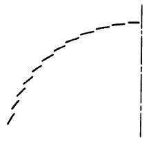
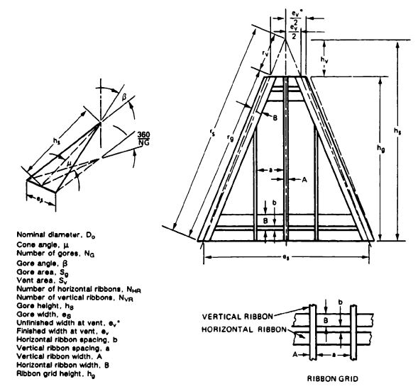
Section 6.2.4 explains the relationship of canopy loading, Failed to parse (SVG (MathML can be enabled via browser plugin): Invalid response ("Math extension cannot connect to Restbase.") from server "https://wikimedia.org/api/rest_v1/":): {\displaystyle W/(C_DS)_p}
; effective porosity, Failed to parse (SVG (MathML can be enabled via browser plugin): Invalid response ("Math extension cannot connect to Restbase.") from server "https://wikimedia.org/api/rest_v1/":): {\displaystyle \lambda_e}
; and vertical ribbon spacing, a. Ribbon parachutes used as final descent parachutes use a vertical ribbon spacing to horizontal ribbon width a/B of 2.5 to 4.0. This spacing allows advantage to be taken of the change in effective porosity. High-canopy-loading ribbon parachutes, such as first-stage drogue chutes, use a vertical ribbon spacing of 1 to 2 to avoid the negative effects of the change in effective porosity. A narrow vertical ribbon spacing of 1.25 times the width of the horizontal ribbon width will be used for the drogue chute.
7.4.8.3 Drogue Chute Summary
Parachute type 30-deg conical ribbon
Parachute diameter Do 13.61 feet
Suspension-line ratio Failed to parse (SVG (MathML can be enabled via browser plugin): Invalid response ("Math extension cannot connect to Restbase.") from server "https://wikimedia.org/api/rest_v1/":): {\displaystyle L_e/D_o} 1.5
Canopy porosity Failed to parse (SVG (MathML can be enabled via browser plugin): Invalid response ("Math extension cannot connect to Restbase.") from server "https://wikimedia.org/api/rest_v1/":): {\displaystyle \lambda_T} 25 to 26%
Vertical to horizontal ribbon spacing a/B 1.25
7.4.9 Canopy Gore Design and Porosity Check
7.4.9.1 Canopy Gore Calculation
Preliminary nominal parachute Failed to parse (SVG (MathML can be enabled via browser plugin): Invalid response ("Math extension cannot connect to Restbase.") from server "https://wikimedia.org/api/rest_v1/":): {\displaystyle D_o} - 13.61 ft (Section 7.4.3)
Number of gores Failed to parse (SVG (MathML can be enabled via browser plugin): Invalid response ("Math extension cannot connect to Restbase.") from server "https://wikimedia.org/api/rest_v1/":): {\displaystyle N_G} = 24
Canopy cone angle Failed to parse (SVG (MathML can be enabled via browser plugin): Invalid response ("Math extension cannot connect to Restbase.") from server "https://wikimedia.org/api/rest_v1/":): {\displaystyle \lambda=30\ deg}
Canopy surface area Failed to parse (SVG (MathML can be enabled via browser plugin): Invalid response ("Math extension cannot connect to Restbase.") from server "https://wikimedia.org/api/rest_v1/":): {\displaystyle S_o = 145.48 ft^2}
Vent area Failed to parse (SVG (MathML can be enabled via browser plugin): Invalid response ("Math extension cannot connect to Restbase.") from server "https://wikimedia.org/api/rest_v1/":): {\displaystyle S_v < 0.01 S_o}
Labeled with the definitions from Figure 7-20, the individual gore dimensions are as follows:
Gore area, Failed to parse (SVG (MathML can be enabled via browser plugin): Invalid response ("Math extension cannot connect to Restbase.") from server "https://wikimedia.org/api/rest_v1/":): {\displaystyle S_g=\frac{S_o}{N_G}=\frac{145.48\ ft^2}{24}=6.06\ ft^2=872.9\ in^2}
Gore half angle, Failed to parse (SVG (MathML can be enabled via browser plugin): Invalid response ("Math extension cannot connect to Restbase.") from server "https://wikimedia.org/api/rest_v1/":): {\displaystyle \beta/2} :
Failed to parse (SVG (MathML can be enabled via browser plugin): Invalid response ("Math extension cannot connect to Restbase.") from server "https://wikimedia.org/api/rest_v1/":): {\displaystyle sin\ \beta/2=cos\mu[sin\frac{360}{2\ N_g}]}
Failed to parse (SVG (MathML can be enabled via browser plugin): Invalid response ("Math extension cannot connect to Restbase.") from server "https://wikimedia.org/api/rest_v1/":): {\displaystyle sin\ \beta/2=cos\ 30\ deg[sin\frac{360}{2.24}]=0.866(0.1305)=0.113 }
Failed to parse (SVG (MathML can be enabled via browser plugin): Invalid response ("Math extension cannot connect to Restbase.") from server "https://wikimedia.org/api/rest_v1/":): {\displaystyle \beta / 2 = 6^{\circ} 29'=6.48\ deg}
Failed to parse (SVG (MathML can be enabled via browser plugin): Invalid response ("Math extension cannot connect to Restbase.") from server "https://wikimedia.org/api/rest_v1/":): {\displaystyle gore\ angle\ \beta=12.96\ deg}
Failed to parse (SVG (MathML can be enabled via browser plugin): Invalid response ("Math extension cannot connect to Restbase.") from server "https://wikimedia.org/api/rest_v1/":): {\displaystyle cos\ \beta/2 = 0.99361}
Failed to parse (SVG (MathML can be enabled via browser plugin): Invalid response ("Math extension cannot connect to Restbase.") from server "https://wikimedia.org/api/rest_v1/":): {\displaystyle tan\ \beta/2 = 0.11368}
Gore radius, Failed to parse (SVG (MathML can be enabled via browser plugin): Invalid response ("Math extension cannot connect to Restbase.") from server "https://wikimedia.org/api/rest_v1/":): {\displaystyle r_S} :
Failed to parse (SVG (MathML can be enabled via browser plugin): Invalid response ("Math extension cannot connect to Restbase.") from server "https://wikimedia.org/api/rest_v1/":): {\displaystyle r_S=[\frac{S_g}{sin\ \beta/2(cos\ \beta/2)}]^{1/2}=[\frac{872.9\ in.^2}{0.1130(0.9936)}]^{1/2}}
Failed to parse (SVG (MathML can be enabled via browser plugin): Invalid response ("Math extension cannot connect to Restbase.") from server "https://wikimedia.org/api/rest_v1/":): {\displaystyle r_S=88.44\ in.}
Gore height, Failed to parse (SVG (MathML can be enabled via browser plugin): Invalid response ("Math extension cannot connect to Restbase.") from server "https://wikimedia.org/api/rest_v1/":): {\displaystyle h_S=r_S(cos\ \beta/2)=(88.44\ in.)(0.99361)=87.87\ in.}
Gore width, Failed to parse (SVG (MathML can be enabled via browser plugin): Invalid response ("Math extension cannot connect to Restbase.") from server "https://wikimedia.org/api/rest_v1/":): {\displaystyle e_S=2r_S(sin\ \beta/2)=(2)(88.44)(0.1137)=20.11\ in. }
Vent area criteria:
- Failed to parse (SVG (MathML can be enabled via browser plugin): Invalid response ("Math extension cannot connect to Restbase.") from server "https://wikimedia.org/api/rest_v1/":): {\displaystyle S_V < 0.01 S_o }
Failed to parse (SVG (MathML can be enabled via browser plugin): Invalid response ("Math extension cannot connect to Restbase.") from server "https://wikimedia.org/api/rest_v1/":): {\displaystyle S_V<0.01(145.48\ ft^2)=1.45ft^2}
2. Failed to parse (SVG (MathML can be enabled via browser plugin): Invalid response ("Math extension cannot connect to Restbase.") from server "https://wikimedia.org/api/rest_v1/":): {\displaystyle D_V \pi \ge 24\ \cdot} width of radial ribbon with no between spacing at vent
Failed to parse (SVG (MathML can be enabled via browser plugin): Invalid response ("Math extension cannot connect to Restbase.") from server "https://wikimedia.org/api/rest_v1/":): {\displaystyle \pi \cdot D_V \ge 24(2.0)=48\ in}
Failed to parse (SVG (MathML can be enabled via browser plugin): Invalid response ("Math extension cannot connect to Restbase.") from server "https://wikimedia.org/api/rest_v1/":): {\displaystyle D_V = \frac{48\ in.}{\pi}=15.28\ in. =1.27\ ft}
Failed to parse (SVG (MathML can be enabled via browser plugin): Invalid response ("Math extension cannot connect to Restbase.") from server "https://wikimedia.org/api/rest_v1/":): {\displaystyle S_V=(15.28)^2(0.7854)=183.37\ in^2= 1.273\ ft^2}
Failed to parse (SVG (MathML can be enabled via browser plugin): Invalid response ("Math extension cannot connect to Restbase.") from server "https://wikimedia.org/api/rest_v1/":): {\displaystyle \frac{S_V}{S_o}=\frac{1.273}{145.48}=0.00875}
Therefore, Failed to parse (SVG (MathML can be enabled via browser plugin): Invalid response ("Math extension cannot connect to Restbase.") from server "https://wikimedia.org/api/rest_v1/":): {\displaystyle \frac{S_V}{S_o}} is less than 1%.
Vent height, Failed to parse (SVG (MathML can be enabled via browser plugin): Invalid response ("Math extension cannot connect to Restbase.") from server "https://wikimedia.org/api/rest_v1/":): {\displaystyle h_V} :
Failed to parse (SVG (MathML can be enabled via browser plugin): Invalid response ("Math extension cannot connect to Restbase.") from server "https://wikimedia.org/api/rest_v1/":): {\displaystyle h_V=r_V(cos\frac{\beta}{2})=\frac{D_V}{2}(cos\frac{\beta}{2}) }
Failed to parse (SVG (MathML can be enabled via browser plugin): Invalid response ("Math extension cannot connect to Restbase.") from server "https://wikimedia.org/api/rest_v1/":): {\displaystyle h_V=7.64(0.9936)=7.59\ in.}
Ribbon grid height, Failed to parse (SVG (MathML can be enabled via browser plugin): Invalid response ("Math extension cannot connect to Restbase.") from server "https://wikimedia.org/api/rest_v1/":): {\displaystyle h_g=87.87-7.59=80.28\ in. }
All previous gore dimensions and the dimensions shown in Figure 7-21 are preliminary. The horizontal ribbon spacing, b, is controlled by the required porosity, Failed to parse (SVG (MathML can be enabled via browser plugin): Invalid response ("Math extension cannot connect to Restbase.") from server "https://wikimedia.org/api/rest_v1/":): {\displaystyle \lambda} . Required changes in horizontal ribbon spacing may result in slight changes in gore and canopy dimensions.
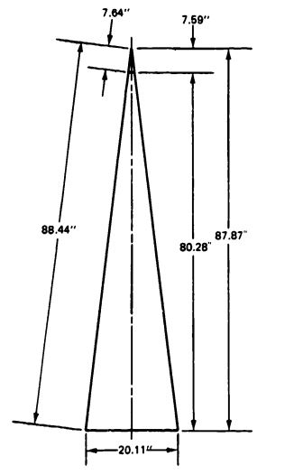
7.4.9.2 Preliminary Gore-Porosity Check
Two methods of calculating gore porosity are in use. The older method, described in Reference 5.39, has been updated in this chapter. This method allows calculation of the porosity for preliminary design purposes when no final gore drawings are available. Reference 2.2 shows how to calculate canopy porosity if a drawing is available based on the ratio of open spaces to total canopy area. Both methods include an estimation of the ribbon (material) porosity.
The total canopy porosity, Failed to parse (SVG (MathML can be enabled via browser plugin): Invalid response ("Math extension cannot connect to Restbase.") from server "https://wikimedia.org/api/rest_v1/":): {\displaystyle \lambda_T=\lambda_g+\lambda_m}
where
Failed to parse (SVG (MathML can be enabled via browser plugin): Invalid response ("Math extension cannot connect to Restbase.") from server "https://wikimedia.org/api/rest_v1/":): {\displaystyle \lambda_g= gore\ porosity,%}
Failed to parse (SVG (MathML can be enabled via browser plugin): Invalid response ("Math extension cannot connect to Restbase.") from server "https://wikimedia.org/api/rest_v1/":): {\displaystyle \lambda_m=canopy\ fabric\ porosity,%}
Figure 7-20 shows that the porosity of a perfect ribbon grid, Failed to parse (SVG (MathML can be enabled via browser plugin): Invalid response ("Math extension cannot connect to Restbase.") from server "https://wikimedia.org/api/rest_v1/":): {\displaystyle \lambda_g} ., can be calculated Failed to parse (SVG (MathML can be enabled via browser plugin): Invalid response ("Math extension cannot connect to Restbase.") from server "https://wikimedia.org/api/rest_v1/":): {\displaystyle t_D} :
Failed to parse (SVG (MathML can be enabled via browser plugin): Invalid response ("Math extension cannot connect to Restbase.") from server "https://wikimedia.org/api/rest_v1/":): {\displaystyle \lambda_{g_{a}}=\frac{porosity\ of\ grid\ area}{total\ grid\ area}=\frac{ab}{(a+A)(b+B)}}
From the evaluation of numerous porosity calculations, the following estimate can be made:
Failed to parse (SVG (MathML can be enabled via browser plugin): Invalid response ("Math extension cannot connect to Restbase.") from server "https://wikimedia.org/api/rest_v1/":): {\displaystyle \lambda_T=\lambda_{ga}-\Delta\lambda}
where
Failed to parse (SVG (MathML can be enabled via browser plugin): Invalid response ("Math extension cannot connect to Restbase.") from server "https://wikimedia.org/api/rest_v1/":): {\displaystyle \Delta\lambda=2\ to\ 3%}
The porosity of a ribbon grid with variations in the distance of the horizontal ribbons is now calculated. The total porosity is estimated, and the most likable horizontal ribbon distance is selected for the first gore-porosity check (Table 7-9). The widths of the vertical ribbon, A, and the horizontal ribbon, B, are fixed values. The ratio of vertical ribbon spacing, to horizontal ribbon width, a/B, was previously selected to 1.25, which is equal to 2.5 inches. A horizontal ribbon distance, b, of 1.1 inches is selected as first approach based on data in Table 7-9.

7.4.9.3 Recheck of Gore Dimensions with Vertical Ribbon Spacing, b, Equal to 1.1 Inches
With b equal to 1.1 inches, a gore recheck is required to determine the resultant number of horizontal ribbons and the gore height. The number of horizontal ribbons, Failed to parse (SVG (MathML can be enabled via browser plugin): Invalid response ("Math extension cannot connect to Restbase.") from server "https://wikimedia.org/api/rest_v1/":): {\displaystyle N_{HR}} , that can be spaced in the gore grid height, Failed to parse (SVG (MathML can be enabled via browser plugin): Invalid response ("Math extension cannot connect to Restbase.") from server "https://wikimedia.org/api/rest_v1/":): {\displaystyle h_c} , is
Failed to parse (SVG (MathML can be enabled via browser plugin): Invalid response ("Math extension cannot connect to Restbase.") from server "https://wikimedia.org/api/rest_v1/":): {\displaystyle N_{HR}=\frac{h_g-B}{(B+b)}=\frac{80.28-2.0}{(2.0+1.1)}=25.25 } (see Figure 7-20)
To avoid a decrease in parachute diameter, 26 horizontal ribbons are selected, changing the gore dimensions from those shown in Figure 7-21 to those shown in Figure 7-22.
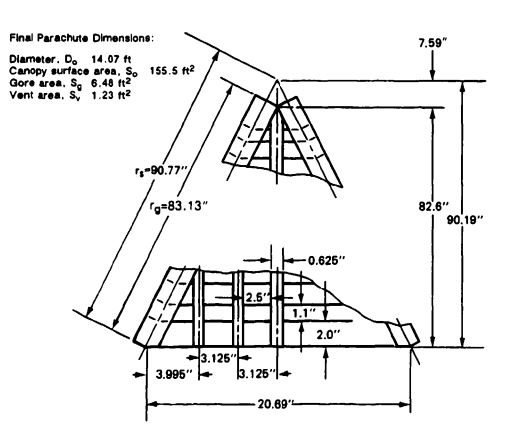
Failed to parse (SVG (MathML can be enabled via browser plugin): Invalid response ("Math extension cannot connect to Restbase.") from server "https://wikimedia.org/api/rest_v1/":): {\displaystyle h_g=26(2.0+1.1)+2.0=[(26)(3.1)]+2=80.6+2.0}
Failed to parse (SVG (MathML can be enabled via browser plugin): Invalid response ("Math extension cannot connect to Restbase.") from server "https://wikimedia.org/api/rest_v1/":): {\displaystyle h_g=82.6\ in.}
Failed to parse (SVG (MathML can be enabled via browser plugin): Invalid response ("Math extension cannot connect to Restbase.") from server "https://wikimedia.org/api/rest_v1/":): {\displaystyle e_S=20.11\frac{82.6}{80.28}=20.69\ in.}
Failed to parse (SVG (MathML can be enabled via browser plugin): Invalid response ("Math extension cannot connect to Restbase.") from server "https://wikimedia.org/api/rest_v1/":): {\displaystyle h_S=h_g+h_V=82.6+7.59=90.19}
Failed to parse (SVG (MathML can be enabled via browser plugin): Invalid response ("Math extension cannot connect to Restbase.") from server "https://wikimedia.org/api/rest_v1/":): {\displaystyle S_g=\frac{e_sh_s}{2}=\frac{20.69(90.19)}{2}=933.02\ in^2=6.48\ ft^2 }
Failed to parse (SVG (MathML can be enabled via browser plugin): Invalid response ("Math extension cannot connect to Restbase.") from server "https://wikimedia.org/api/rest_v1/":): {\displaystyle S_o=24\ S_g=24(6.48\ ft^2)=155.5\ ft^2 }
Failed to parse (SVG (MathML can be enabled via browser plugin): Invalid response ("Math extension cannot connect to Restbase.") from server "https://wikimedia.org/api/rest_v1/":): {\displaystyle D_o=1.1284\sqrt{S_o}=1.1284\sqrt{155.5}=14.07\ ft }
Gore radius, Failed to parse (SVG (MathML can be enabled via browser plugin): Invalid response ("Math extension cannot connect to Restbase.") from server "https://wikimedia.org/api/rest_v1/":): {\displaystyle r_S=h_S\frac{1}{cos\ \beta/2} }
Failed to parse (SVG (MathML can be enabled via browser plugin): Invalid response ("Math extension cannot connect to Restbase.") from server "https://wikimedia.org/api/rest_v1/":): {\displaystyle r_S=90.19 \frac{1}{0.99361}=90.77\ in. }
Radius of ribbon grid height, Failed to parse (SVG (MathML can be enabled via browser plugin): Invalid response ("Math extension cannot connect to Restbase.") from server "https://wikimedia.org/api/rest_v1/":): {\displaystyle r_g=h_g\frac{1}{cos\ \beta/2}=\frac{82.60}{0.99361}=83.13\ in. }
The number of vertical ribbons, Failed to parse (SVG (MathML can be enabled via browser plugin): Invalid response ("Math extension cannot connect to Restbase.") from server "https://wikimedia.org/api/rest_v1/":): {\displaystyle N_{VR} }
, is five, based on free spacing of 2.5 inches and horizontal ribbon spacing, b, of 1.1 inches.
This change in diameter from 13.67 to 14.07 feet increases the parachute drag area by 6%, decreases the final rate of descent by about 3%, leaves the reefed opening force unchanged, and slightly increases the disreef opening force.
7.4.9.4 Gore-Porosity Recheck
Geometric gore porosity, Failed to parse (SVG (MathML can be enabled via browser plugin): Invalid response ("Math extension cannot connect to Restbase.") from server "https://wikimedia.org/api/rest_v1/":): {\displaystyle \lambda_g =\lambda_{ga}+[\frac{S_v^*}{S_o}[\frac{100-\lambda_{ga}}{100}]]-[\frac{S_{RR}}{S_o}\lambda_{ga}]}
Grid porosity, Failed to parse (SVG (MathML can be enabled via browser plugin): Invalid response ("Math extension cannot connect to Restbase.") from server "https://wikimedia.org/api/rest_v1/":): {\displaystyle \lambda_{ga} = 2.39% } (See Table 7-9.)
Open vent area, Failed to parse (SVG (MathML can be enabled via browser plugin): Invalid response ("Math extension cannot connect to Restbase.") from server "https://wikimedia.org/api/rest_v1/":): {\displaystyle S_v=1.272-0.59^*=0.683\ ft^2}
Canopy area, Failed to parse (SVG (MathML can be enabled via browser plugin): Invalid response ("Math extension cannot connect to Restbase.") from server "https://wikimedia.org/api/rest_v1/":): {\displaystyle S_o=155.50\ ft^2}
Area of radial ribbons, Failed to parse (SVG (MathML can be enabled via browser plugin): Invalid response ("Math extension cannot connect to Restbase.") from server "https://wikimedia.org/api/rest_v1/":): {\displaystyle S_{RR}=(r_g)(B)(N_{SL})=(83.7\ in.)(2.0\ in.)(24) = 4017.6^2\ in.=27.90\ ft^2}
Failed to parse (SVG (MathML can be enabled via browser plugin): Invalid response ("Math extension cannot connect to Restbase.") from server "https://wikimedia.org/api/rest_v1/":): {\displaystyle \lambda_g=28.39+[\frac{0.683}{155.50}[\frac{100-28.39}{100}]]=[\frac{27.90}{155.50}28.39]}
Failed to parse (SVG (MathML can be enabled via browser plugin): Invalid response ("Math extension cannot connect to Restbase.") from server "https://wikimedia.org/api/rest_v1/":): {\displaystyle =28.39+[(0.0044)(0.7161)]-[(0.179)(28.39)]}
Failed to parse (SVG (MathML can be enabled via browser plugin): Invalid response ("Math extension cannot connect to Restbase.") from server "https://wikimedia.org/api/rest_v1/":): {\displaystyle =28.39+0.0032-5.08=23.31%}
Area covered by vent bands.
Material porosity,
Failed to parse (SVG (MathML can be enabled via browser plugin): Invalid response ("Math extension cannot connect to Restbase.") from server "https://wikimedia.org/api/rest_v1/":): {\displaystyle \lambda_m=\frac{\lambda_m^*}{27.4}[1.0-[\frac{\lambda_g}{100.0}+\frac{S_V+S_{RR}+S_{VR}+S_{ST}}{S_o}]]}
Ribbon Specification Porosity, Failed to parse (SVG (MathML can be enabled via browser plugin): Invalid response ("Math extension cannot connect to Restbase.") from server "https://wikimedia.org/api/rest_v1/":): {\displaystyle \lambda m^*}
:
The upper half of the gore uses 500-pound ribbon; Failed to parse (SVG (MathML can be enabled via browser plugin): Invalid response ("Math extension cannot connect to Restbase.") from server "https://wikimedia.org/api/rest_v1/":): {\displaystyle \lambda} = 0. The lower half, encompassing 75% of the gore area, uses 300-pound ribbon; Failed to parse (SVG (MathML can be enabled via browser plugin): Invalid response ("Math extension cannot connect to Restbase.") from server "https://wikimedia.org/api/rest_v1/":): {\displaystyle \lambda = 150\ ft^3/ft^2/min. }
The conversion from material porosity to geometric porosity at 1/2-inch Failed to parse (SVG (MathML can be enabled via browser plugin): Invalid response ("Math extension cannot connect to Restbase.") from server "https://wikimedia.org/api/rest_v1/":): {\displaystyle H_2O} pressure is Failed to parse (SVG (MathML can be enabled via browser plugin): Invalid response ("Math extension cannot connect to Restbase.") from server "https://wikimedia.org/api/rest_v1/":): {\displaystyle 27.4\ ft^3/ft^2\ min=1%\ \lambda} . Therefore,
Failed to parse (SVG (MathML can be enabled via browser plugin): Invalid response ("Math extension cannot connect to Restbase.") from server "https://wikimedia.org/api/rest_v1/":): {\displaystyle \lambda_{m_{grid}}=\frac{150(0.75)}{27.4}=4.1%}
Failed to parse (SVG (MathML can be enabled via browser plugin): Invalid response ("Math extension cannot connect to Restbase.") from server "https://wikimedia.org/api/rest_v1/":): {\displaystyle S_V=0.683\ ft^2}
Failed to parse (SVG (MathML can be enabled via browser plugin): Invalid response ("Math extension cannot connect to Restbase.") from server "https://wikimedia.org/api/rest_v1/":): {\displaystyle S_{RR}=27.90\ ft^2 }
Area of vertical ribbon covering horizontal ribbon, Failed to parse (SVG (MathML can be enabled via browser plugin): Invalid response ("Math extension cannot connect to Restbase.") from server "https://wikimedia.org/api/rest_v1/":): {\displaystyle S_{VR}} :
Failed to parse (SVG (MathML can be enabled via browser plugin): Invalid response ("Math extension cannot connect to Restbase.") from server "https://wikimedia.org/api/rest_v1/":): {\displaystyle S_{VR}=N_G\frac{N_{VR}}{2}A[h_g-[(N_{HR}-1)6]]=(24)(\frac{5}{2})(0.625)[82.6((27-1)1.1)]}
Failed to parse (SVG (MathML can be enabled via browser plugin): Invalid response ("Math extension cannot connect to Restbase.") from server "https://wikimedia.org/api/rest_v1/":): {\displaystyle =38.7[82.60-((26)(1.1))]=(38.7)(54.0)=2089.80\ in^2}
Failed to parse (SVG (MathML can be enabled via browser plugin): Invalid response ("Math extension cannot connect to Restbase.") from server "https://wikimedia.org/api/rest_v1/":): {\displaystyle =14.51\ ft^2}
Area of skirt band, Failed to parse (SVG (MathML can be enabled via browser plugin): Invalid response ("Math extension cannot connect to Restbase.") from server "https://wikimedia.org/api/rest_v1/":): {\displaystyle S_{SB}}
:
Failed to parse (SVG (MathML can be enabled via browser plugin): Invalid response ("Math extension cannot connect to Restbase.") from server "https://wikimedia.org/api/rest_v1/":): {\displaystyle S_{SB}=N_ge_S=(24)(20.69\ in.)=496.56\ in^2=3.45\ ft^2}
Failed to parse (SVG (MathML can be enabled via browser plugin): Invalid response ("Math extension cannot connect to Restbase.") from server "https://wikimedia.org/api/rest_v1/":): {\displaystyle \lambda_m=\frac{(150)(0.75)}{27.4}[1.0-(\frac{23.31}{100}+\frac{0.683+27.90+14.51+3.45}{155.50})]}
Failed to parse (SVG (MathML can be enabled via browser plugin): Invalid response ("Math extension cannot connect to Restbase.") from server "https://wikimedia.org/api/rest_v1/":): {\displaystyle =4.106[1.0-(0.2331+\frac{46.543}{155.50})]=4.106[1.0-0.5324]}
Failed to parse (SVG (MathML can be enabled via browser plugin): Invalid response ("Math extension cannot connect to Restbase.") from server "https://wikimedia.org/api/rest_v1/":): {\displaystyle =(4.106)(0.4676)=1.92%}
Total canopy porosity, Failed to parse (SVG (MathML can be enabled via browser plugin): Invalid response ("Math extension cannot connect to Restbase.") from server "https://wikimedia.org/api/rest_v1/":): {\displaystyle \lambda_T=\lambda_g+\lambda_m=23.31+1.92=25.23%} . This porosity falls into the specified range of 25 to 26% as established in Table 7-6. Porosity should be cross-checked with the method outlined in Reference 2.2.
7.4.9.5 General Comments on Gore Design and Porosity Selection
The canopy gore design-total canopy porosity, XT; spacing of vertical ribbon; size of vent; and pocket-band arrangement-are the primary design features that determine the aerodynamic performance of the parachute. The most important characteristics of parachute performance are stability, smooth opening, drag, and opening-force coefficients.
Determining porosity under a no-load condition is rather unrealistic, because most of the important aerodynamic characteristics occur under high-load conditions (opening shock) or medium-load conditions (descent). However, since the beginning of parachute development, aerodynamic parachute characteristics obtained in wind-tunnel and free-flight tests have been related to fixed design dimensions such as diameter and porosity.
Determining the effective porosity caused by the changing load during the opening process and by the venetian-blind effect of the ribbon grid design is practically impossible. Furthermore, the change in effective porosity is similar on all ribbon parachutes because of the similarities of the ribbon grid designs, load factors, and related changes in material elongation that cause deformation of the ribbon grids and the parachute canopies.
7.4.9.6 Computer Programs for Determining Gore Design and Porosity Calculation
Both gore design and porosity calculations can be determined by computer programs. Organizations involved in frequent design of ribbon parachutes should establish these programs.
7.4.10 Ribbon Parachute Canopies with Continuous Horizontal Ribbons
Ribbon parachute canopies are frequently designed and manufactured with continuous horizontal ribbons either in single or two-section canopies. The continuous ribbon design decreases weight and volume, increases the strength of the horizontal ribbon-radial connection, and simplifies manufacturing. Continuous horizontal ribbons change the porosity characteristics of the canopy.
Figure 7-19 shows how the individual horizontal ribbons orient themselves in a canopy manufactured from individual triangular gores. In the inflated canopy, the horizontal ribbons in the canopy crown area orient parallel to the canopy design. However, in the skirt area, the canopy design line is almost parallel to the airflow. This design, usually called the "venetian blind effect," causes the longer leading edge of each horizontal ribbon to bulge out and position the ribbon with a positive angle of attack to the airflow. The result is an increase in effective porosity under high dynamic pressure conditions. The venetian blind effect is discussed in section 6.2.4, and the influence of canopy loading on the change in effective porosity is shown in Figure 6-24.
Designing canopies with continuous horizontal ribbons changes the venetian blind effect. Returning to Figure 7.19, it is obvious that continuous horizontal ribbons in the canopy skirt area do not bulge out since leading and trailing ribbon edges have the same length and do not position themselves with an angle of attack to the airflow. However, in the crown area of the canopy where each gore forms a triangle, the equal length of the leading and trailing ribbon edges now gives each ribbon a negative angle of attack thereby increasing the effective porosity in the canopy crown area. The effect is minimized by large number of gores arid by the use of a center vertical ribbon, or a miniradial, as Sandia engineers call it.
Discussion with Sandia and industry personnel indicates that no measurable difference has been found in the aerodynamic characteristics of ribbon parachute canopies designed with individual gores or with continuous horizontal ribbons so long as the canopies contain a large number of gores and a center vertical ribbon. However, a slight delay in initial inflation seems to occur on small parachutes with a small number of gores. Closer spacing of vertical ribbons in the canopy crown area should counteract this delay. Another method of counteracting the delay is by gathering the trailing edges of horizontal ribbons with several rows of stitching and using a lower porosity in the crown area.
7.4.11 Use of Kevlar Fabrics
Many modern ribbon parachutes use Kevlar suspension lines, risers, and canopy skirt, lateral, and vent tapes, which results in a decrease in weight and volume. Section 6.5.5 discusses all aspects of working with Kevlar in the design of parachute assemblies. This includes physical characteristics of Kevlar fibers and fabrics, available Kevlar fabrics, and experience in designing in Kevlar. Section 6.6.5 should be studied before designing in Kevlar.


![{\displaystyle [{\frac {W}{(C_{D}S)_{p}}}]}](https://wikimedia.org/api/rest_v1/media/math/render/svg/abf8c8943d037e4086c01a30f836e1968f93196a)
![{\displaystyle [{\frac {W}{(C_{D}S)_{p}]}}]}](https://wikimedia.org/api/rest_v1/media/math/render/svg/b84bbb28138a4805f0086460fe70a7309e80c9e4)


