Recovery System Application
8.1 APPLICATIONS ANALYSIS
Parachutes are the primary means of aerial recovery and landing of air and space vehicles; aircrew emergency escape; retardation of ordnance; airdrop of military troops and supplies; premeditated use by sport parachutists, rescue personnel, and smoke jumpers; and other applications. The Recovery Systems Design Guide (Reference 2.1) describes many parachute recovery systems applications in use through 1977. This chapter describes parachute applications in use or being developed since 1978.
Different applications require a variety of parachute types. Tables 5-1 through 5-5 list 29 different parachute and inflatable decelerator types. Table 8-1 lists parachute design criteria that apply to all parachute applications. These criteria are useful in understanding why a particular parachute was used for a specific application described in this chapter.

Reliability of operation is understandably the number one requirement for all parachute applications. Each parachute listed in the tables opens reliably when deployed in airflow in the velocity range suitable for that particular parachute. Parachute inflation problems are introduced by installation, forebody wake, air vehicle instability, interference with vehicle protrusion in the path of the deploying parachute, and velocity and altitude problems—all factors that must be considered in the preliminary selection of the parachute assembly, installation, and deployment concept. Other criteria, such as stability, low opening forces, simplicity of design, suitability for the mission altitude, and environmental profile narrow the choices but frequently leave several candidates for the choice of main descent parachute(s). This main descent parachute contributes the largest percentage of the weight and volume of the parachute assembly. For otherwise equal performance, weight and volume are generally the deciding factors for main descent parachute selection. The use of parachute reefing and parachute clusters gives the design engineer a chance to control parachute opening forces and stability and allows the use of high drag parachutes that, as a rule, have high opening forces and poor stability.
For specific parachute applications (air vehicles, aircrew escape, ordnance retardation), the requirements of minimum weight and especially of minimum volume outweigh parachute assembly cost considerations. Parachute assemblies, as shown in Figure 6-61, constitute 8 to 12% of the total vehicle weight; this increases to 12 to 15% if an impact-attenuation system is added. The parachute recovery system, ballast during the operational mission, is needed only for final recovery. Every pound saved in the parachute assembly allows greater payload, range, or mission-oriented on-board equipment. The ever-increasing use of Kevlar in primary load carrying members, a very important step in parachute development, can reduce the weight of parachute assemblies by 25 to 40%, depending on the amount of Kevlar used. Newer materials. such as Spectra, may further reduce weight and volume.
One criterion for judging the weight effectiveness of parachutes is the amount of parachute drag area produced per pound of parachute weight. (CDS)p/Wp, this criterion is called the "weight effectiveness" in this manual. Weight effectiveness is automatically related to volume effectiveness: the lower the parachute assembly weight, the lower the required volume for storing the parachute assembly. The size, and hence the required drag area and resultant weight of the main parachute(s), are determined by the permissible rate of descent at landing. Table 8-2 compares the weight effectiveness of parachutes manufactured from nylon fabric and from a hybrid nylon/Kevlar fabric. The weight effectiveness of well-designed nylon parachutes reaches 65 square feet (ft2) of drag area per pound of parachute weight. Hybrid parachutes using nylon for the canopy and Kevlar for suspension lines, canopy tapes, and radials reach 85 ft2 of drag area per pound of parachute weight. Kevlar will help alleviate the ever-present problem of vehicle weight growth during development and vehicle life. The weight of the F-111 aircraft crew module, the Teledyne Ryan Firebee target drone, and the Mercury and Apollo spacecraft grew by 25 to 80% with no permissible increase in vehicle rate of descent, parachute compartment volume. or parachute opening forces taken by the vehicle hard points. Past attempted solutions have often involved higher parachute pack density. When initial design of the parachute recovery system must include a high pack density for the parachute assembly, costly and time-consuming vehicle redesign may be necessary to accommodate the required larger parachute(s). For new vehicles, the prime contractor and the recovery system subcontractor should take into account unavoidable vehicle growth. A pack density in the 30 to 35 lb/ft3 range allows an increase in parachute size, weight, and volume of approximately 35% using a pack density in the 45 Ib/ft3 range. Planning for vehicle weight increase and the requirement for a larger, more voluminous parachute assembly appear to be the rule in designing parachute recovery and retardation systems.

8.2 AIR AND SPACE VEHICLE RECOVERY
This section describes the parachute recovery systems for the U.S. Navy supersonic low-altitude target drone SLAD, the Navy and Air Force cruise missile midair retrieval systems, and the Canadian CL 289 reconnaissance drone)
8.2.1 AQM-127A Supersonic Low-Altitude Target (SLAT)
The SLAT vehicle duplicates the attack of a fast, on-the-deck flying missile against Navy ships. The SLAT can fly at supersonic speed and high altitude and dive from outside the effective range of ship defenses for an on-the-deck attack. Parachute recovery is initiated by vehicle pull up about 1 mile prior to target contact, and parachute deployment is initiated at Mach 0.5 at an altitude of 5000 to 10,000 feet. Drone recovery is possible over land and water. The parachute system consists of a drogue-chute assembly and a single main parachute assembly with different main parachutes for land or water landing. Parachute deployment starts with the pyro-ejection of the parachute compartment cover located on the upper side of the vehicle, shown in Figure 8-1; this ejection also extracts a small pilot chute that, in turn, deploys a 4.2-foot diameter, conical ribbon drogue-chute. This drogue chute has a small amount of fixed reefing for increased stability in the wake of the drone forebody. The drogue chute decelerates the drone, pulls it into a high angle of attack attitude, and after 13 seconds, disconnects and deploys the main recovery parachute. Both the drogue and the main parachute are reefed in two stages for opening-force control to a 3-g level. A 48-foot diameter polyconic, solid fabric parachute is used for water landing. Flotation bags located in the parachute compartment and inflated with nitrogen to 3000 psi are deployed 36 seconds after the recovery command. The flotation bags float the missile in a 30-degree, nose-high attitude in the water. A bridle connecting the tops of the two flotation bags serves as the contact point for helicopter hookup during water retrieval.
A 63-foot-diameter polyconic parachute is used to land the 1200-pound target drone on land at a rate of descent of 18 ft/s in a slightly nose-high attitude. Both main parachutes use standard-porosity nylon fabric for the canopy and Kevlar for canopy tapes, radials, suspension lines, and risers. The weight effectiveness (square foot of drag area per pound of parachute weight) is 70.5 lb/ft2, a good value. No impact attenuation system is required at the 18 ft/s rate of descent.
8.2.2 CL 289 Reconnaissance Drone
The CL 289 reconnaissance drone with a recovery weight of approximately 375 pounds is the successor to the CL 89 reconnaissance drone developed in the early 1960s in Canada. The parachute landing system, developed by Irvin Canada, uses parachutes for deceleration and descent, and air bag for ground impact attenuation; the recovery system incorporates several innovative features. Figure 8-2 (Reference 8.1) shows the landing sequence A fast drone turnaround time necessitates a precise landing in a preselected area, an undamaged drone after landing, and quick removal of the used and fast installation of a refurbished parachute air bag system.
.

Recovery after a completed mission starts at about 250 knots with ejection of the parachute compartment cover located on the aft underside of the vehicle. The cover extracts a 5.58-foot diameter, conical ribbon drogue chute that decelerates and stabilizes the drone, and after 6 seconds, disconnects and deploys the 31-foot diameter conical ribbon main parachute that lowers the drone at a rate of descent of 31 ft/s. Both ribbon parachutes have variable porosity nylon canopies with lower porosity at the crown and higher porosity at the skirt area. The main parachute is equipped with an internal web chute for inflation control. The developer states that both features, the varied canopy porosity and the internal web chute, provide a more controlled and uniform canopy inflation. The working of the internal web chute is explained in Reference 5.89. A stable main descent parachute is required for proper air bag operation. The ribbon parachute was probably chosen based upon the positive experience with a similar parachute on the CL 89 drone. Both the drogue and the ribbon main parachutes are modem designs with continuous horizontal ribbons; a mostly nylon canopy; and Kevlar risers, suspension lines, and canopy reinforcing tapes. The parachute assembly is stored in a removable metal container packed to a density of 53 lb/ft3, a very high value. Using today's knowledge, a reefed cross parachute with good stability, and with a 29% higher drag than the ribbon parachute, the main parachute may somewhat relieve the high pack density problem.
The air bag design is shown in Figure 8-3. Both the nose and tail bags are two-compartment bags. One compartment works as the impact attenuator and the other compartment stays inflated and keeps the drone off the ground. Two interesting air bag features are the rollover protection provided by the nose air bag that wraps around the cylindrical drone body (shown in Figure 8-3) and the design of the air bag pressure relief valves (shown in Figure 8-4 and shown previously as Figure 6-81). When the internal bag pressure reaches the operational pressure level, sleeves manufactured from stretch fabric expand and meter the air out of the bags, using the variable porosity characteristics of the stretch fabric to control the permissible deceleration level for various landing conditions, an elegant design approach. Reference 8.1 documents the design and testing of the parachute air bag landing system. The weight effectiveness of the main parachute, approximately 39 lb/ft2, is relatively low. However, the use of air bag attenuators necessitates the use of a stable, and therefore low-drag, main parachute. Ribbon parachutes are stronger and heavier and can stand a lot of abuse, including high deployment speed and multiple reuses.

.jpg)
8.2.3 Midair Retrieval of the USAF AGM-86B Air Launched Cruise Missile
The midair retrieval system (MARS) for the Air Force air launched cruise missile (ALCM) has two functions. MARS allows retrieval by helicopter after a training mission is completed and allows ground recovery of the missile if the training flight must be aborted. An annular parachute as main descent parachute and a ringsail engagement parachute form an effective MARS parachute assembly.

In the flight termination mode, a drogue chute is used for high-speed deceleration at dynamic pressures up to 900 lb/ft2 and altitudes up to 40,000 feet. The annular parachute is deployed at 15,000 feet and ground-recovers the missile. In the MARS mode, the drogue chute is bypassed, and midair retrieval takes place starting at 19,000 feet. The annular main and ringsail engagement parachute assembly is shown in Figure 8-5. A vehicle weighing up to 2000 pounds can be lowered by the 71.6-foot-diameter annular parachute at a rate of descent of 23.6 ft/s from an altitude of 10,000 feet. The development of the annular parachute concept and related airfoil parachute is described in References 5.37 and 5.38. The 22.3-foot-diameter ringsail engagement parachute is located above and is closely coupled to the main parachute. The annular parachute has a vent opening equal to 65% of the inflated canopy diameter. Airflow through this large vent inflates the ringsail engagement parachute. resulting in a very stable parachute assembly with no independent movement in the engagement parachute.

Figure 8-6 shows the parachute deployment sequence. Different signals initiate either the midair retrieval or the flight termination ground recovery. Both signals initiate ejection of the parachute compartment cover located on the vehicle underside. The cover simultaneously extracts a light design, 5.9-foot-diameter ringslot pilot chute and a strong, 1.8-foot-diameter ribbon pilot chute. At high-speed deployment, the large, light design pilot chute breaks away and the ribbon pilot chute deploys a 6.6-foot-diameter ribbon drogue chute. The missile descends on this drogue chute and, at 15,000 feet, disconnects and deploys the main parachute assembly for ground recovery. The MARS mode deployment sequence begins at 19,000 feet and at a low deployment speed. The large pilot chute bypasses the ribbon drogue chute and deploys the main parachute assembly as demonstrated in Figure 8-6. The time from cover ejection to ready-for-action main parachute is 24 seconds and is tailored to limit the parachute opening forces to 3 g for a 2000-pound vehicle. The vehicle turns over during the parachute deployment process. The helicopter, upon making contact with the engagement parachute, a load line that runs around the engagement parachute, down the engagement parachute suspension line and the main parachute, to a disconnect at the V-riser junction point. The intricate deployment, reefing, engagement, and parachute disconnect systems are described in Reference 8.3. Extensive use of Kevlar for the ribbon drogue and, where appropriate, for the main parachute assembly, decreases weight and volume. allowing stowage in a very limited parachute compartment at a pack density of 51 lb/ft3 (using form setting by autoclaving under vacuum and heat application). A 6-foot-diameter cross parachute is used for stabilizing the missile during helicopter tow.
The Navy AGM-109 cruise missile uses the tandem parachute concept for helicopter midair retrieval after training missions are completed. Figure 8-7 shows the parachute deployment and midair retrieval sequence. The parachute system consists of a 71.8-foot-diameter triconical, gliding, main descent parachute and a 16.4-foot-diameter ringslot engagement parachute connected to the main parachute; the missile has a 13,600-pound Kevlar load line. Previous tandem systems for midair retrieval had problems maintaining tension in the heavy load line, poor yaw stability of the main parachute, and the engagement parachute trailing outside the wake of the main parachute.

These are characteristics that make it difficult for the helicopter to catch the engagement parachute in the proper position to disconnect the load line. Pioneer Parachute Co., Inc., Manchester, Conn., developed a tandem parachute system for the AGM-109 missile that overcomes the problems mentioned above. This system includes a lightweight Kevlar load line and a gliding main parachute with a glide ratio of 0.65 and a yaw stability of better than 1 degree per second. Gliding is obtained by venting two sections in each of 16 gores in the 64-gore canopy; this, together with stabilizing vents, provides for a stable gliding parachute with the engagement parachute trailing at a 65-degree attitude toward the main parachute, shown in sequence 8 of Figure 8-7. The tandem parachute assembly is detailed in Figure 8-8 and the vented canopy in Figure 8-9. Figures 8-7 through 8-9 are taken from Reference 8.4, which gives a detailed description of the development and testing of this tandem concept.
Upon deployment command, the missile performs a pull-up maneuver. When the dynamic pressure decreases to 80 lb/ft2, the cover of the parachute compartment is pyro-ejected, and an attached lanyard deploys a 24-inch pilot chute that in turn deploys a 60-inch-diameter guide surface parachute, which then extracts the main parachute assembly. The tandem parachute assembly uses nylon for the parachute canopy and Kevlar for the load line, main parachute suspension lines. and canopy reinforcing tapes. The parachute assembly is pressure packed to a density of 43 lb/ft3, heat cycled during packing, and autoclaved at 180° F after packing for 20 hours to maintain form stability of the packed parachute. The weight effectiveness of the triconical main parachute expressed in square feet of drag area produced per pound of weight is 83.7 ft3/lb, a high value.


8.2.5 Space Shuttle Solid Booster Rocket Parachute Recovery
The parachute recovery system for the three solid rocket boosters (SRBs) of the NASA Space Shuttle is described in Chapter 2 of Reference 2.1. The 175,000-pound steel casing boosters descend into the atmosphere broadside, thereby decelerating the booster to about Mach 0.6 at altitude of 16,000 feet. A single, 56-foot-diameter conical ribbon parachute, reefed in two steps. decelerates and stabilizes the booster. At 6000 feet, three 115-foot-diameter conical ribbon parachutes decelerate the booster to a water entry velocity of 85 ft/s. This system successfully recovered the SRBs in 10 out of 11 flights. References 6.41 and References 8.5 to 8.11 detail individual development and test phases of the SRB parachute recovery system.
Two problems developed. (1) The water entry velocity, 85 ft/s, established in model drop tests did not prevent structural damage in the booster shells. (2) The development of a carbon-epoxy filament-wound booster casing decreased the booster weight and changed its mass properties, which resulted in higher reentry velocities and necessitated the development of a stronger, first-stage drogue chute.
To solve the water entry problem, the diameter of each of the three main descent parachutes was increased to 136 feet. The result was a 20-degree conical ribbon parachute with a canopy porosity of 15%, having 160 gores. suspension lines with a length 1.5 times the diameter and weighing 2159 pounds.
The parachute is reefed in two steps, with the opening force per parachute limited to 175,000 pounds. To avoid differential elongation in the 204-foot-long suspension lines (discussed in section 6.6), the lines are interspaced in three sections. The parachute is packed to a density of 39 lb/ft3. Reference 8.10 describes the development and testing of the 136-foot-diameter ribbon main parachute.
As of January 1989, both were recovered on 27 out of 29 Space Shuttle flights, with the first 13 flights using the 115-foot•diameter ribbon main parachutes and the remaining flights using the larger 136-foot-diameter parachutes. Individual drogue chutes have been used five times and the main parachutes, designed for 20 uses, have been used four times so far without having reached their useful life limits.
Future Space Shuttle launches from Vandenberg Air Force Base, Calif., will use the carbon-epoxy filament-wound case SRBs that are approximately 30,000 pounds lighter than the present 175,000-pound steel casing SRBs. A change in the mass properties of this booster will cause a change in a wide range of drogue chute deployment conditions, from low speed to deployment close to Mach 1 at 16,000 feet. This requires a stronger drogue chute to accommodate the higher dynamic pressure. The drogue chute diameter was reduced to 52.5 feet, and the design load increased to 375,000 pounds. The 20-degree conical ribbon parachute has a porosity of 20% and has 72 gores and suspension lines, with a 15,000-pound strength and a length equal to 1.8 times the diameter of the canopy. The parachute is reefed in two steps with Kevlar reefing lines; the rest of the parachute and riser are manufactured from nylon. The diameter of the pilot chute was reduced to 10 feet to comply with the available compartment volume. Deployment of the pilot chute/drogue chute combination over the required velocity range was investigated in pilot chute deployment tests at the Supersonic Naval Ordnance Research Track (SNORT), Naval Weapons Center, Calif. (Reference 8.11).
Aerial tests using a 50,000-pound test vehicle dropped from a B-52 aircraft were also conducted at the Naval Weapons Center. During one of these aerial drop tests in an overload condition, a parachute force of 471,000 pounds was recorded — probably the highest parachute load ever measured on a successful test. Numerous design, installation, and deployment problems encountered during the development of this almost 2000-pound drogue chute had to be solved as described in References 8.10 and 8.11. Use of this stronger drogue chute awaits use of the filament-wound composite casings.
8.3 AIRCREW EMERGENCY ESCAPE PARACHUTE SYSTEMS
8.3.1 Escape System Concepts
In Chapter 2 of Reference 2.1, requirements for and methods of recovering aircrews in case of aircraft emergencies are discussed in detail. Following are five methods of aircrew emergency escape now being used.
| Manual Bailout. The aircrew exits the aircraft over the side of the cockpit, through a door or an escape hatch. A manually or automatically opening parachute, equipped with a lock set above 15,000 feet, is used for deceleration, descent. and landing. The manual bailout method is still used on military trainers and on transport aircraft. Manual bailout is limited to velocities below 300 knots because of difficulties in leaving the aircraft and the danger of contact with the aircraft. Tables 8-3 and 8-4 list Navy and Air Force personnel emergency parachutes used for manual bailout.
Tractor Rocket Extraction. As the name implies, the aircrew is pulled out and away from the aircraft by a tractor rocket. This extraction method uses an automatic parachute for recovery and landing. Often called the Yankee system, this method is used for military trainers, and has been used for emergency escape during flight testing of commercial aircraft. The danger of contact with the aircraft limits the velocity in this concept. Ejection Seat. In the ejection-scat method, the crew member and the seat are ejected out of the aircraft on rails and then shot upward and away from the aircraft by rockets. A multiple parachute assembly decelerates and stabilizes the seat with the crew member remaining in the seat. At the proper altitude, or at the proper speed at low altitude, seat and crew member separate and the main descent parachute opens. Frequently, the opening main parachute is used to pull the crew member away from the seat. The separation of the crew member from the seat, and proper timing of main parachute deployment, require altitude and pressure sensors and multimode sequences for control of parachute deployment in the velocity-altitude range from zero on-the-deck to Mach 3 at altitudes approaching 100,000 feet. High dynamic pressure makes it difficult to restrain the limbs of the crew member and retain protective headgear. Multiple crew member ejection requires staggered timing and proper scat separation to avoid seat collisions and parachute interference. Encapsulated Seat. The encapsulated seat method uses an ejection seat where the crew member is protected against air blast (high dynamic pressure) by a clamshell-type shield that folds over the seat from top and bottom or from the sides. Encapsulated seats used on the B-58 and B-70 bombers required parachute stabilization and retardation at high speeds and altitude, main parachutes for descent and landing, and impact attenuation for absorbing the landing impact, Crew members using both seats appreciated the protected environment and that some of the rescue and survival gear was moved from the parachute harness assembly to the encapsulated seats, Crew Module. A crew module permits the aircraft crew to fly in a semishort sleeve environment. The crew module normally encompasses the aircraft cockpit cut from the fuselage by rocket-ejected from the aircraft, and rocket or fin-stabilized until the stabilization and retardation drogue chute becomes effective. The drogue chute assembly lowers the crew module to the allowable opening speed or altitude for main parachute deployment. Crew modules need ground-impact/attenuation systems. The ground-impact/attenuation systems, in turn, require a stable main parachute assembly. High drag parachutes in clusters are frequently used for the crew module method. Crew module parachute systems are designed for low g forces related to the deceleration limit of the human body. |
Parachute assemblies designed for low opening forces using multiple reefing also result in a decrease in the weight of the parachute system. A parachute assembly designed for 3.g equivalent opening forces weighs 40% less than a parachute assembly designed for 6.g equivalent forces. A main parachute assembly designed for ground impact forces not to exceed 6 g would require a very low rate of descent and would result in excessively large and heavy parachutes. Frangible impact attenuators have been used on the B-58 encapsulated seat, and air bags on the B-70 encapsulated seat and the F-111 crew modules. Studies indicate that a parachute retrorocket impact attenuation system will provide the minimum weight system. Parachute/air bag and parachute retrorocket systems are not very flexible with regard to rate of-descent variations caused by weight increases and changes in landing altitude (see section 6.8). The main parachute assembly should be installed at a low pack density in the 30-1b/ft3 range, allowing the installation of a larger parachute at a higher pack density.
Operational escape vehicles had the following empty weights per crew member:
| Ejection seats | 150 to 175 lb/crew member |
| Encapsulated seats | 400 to 500 lb/crew member |
| Crew modules | 1200 to 1400 lb/crew member |
References 8.12 to 8.14 describe past and present aircrew emergency situations as well as possible development trends.
8.3.2 Military Personnel Emergency Parachute Types
The Navy and Air Force personnel emergency parachute assemblies used for individual bailout and for bailout in ejection seats are listed in Tables 8-3 and 8-4. respectively. These tables update information contained in Tables 1-4 and 1-5 in the Air Force Recovery System Design Guide. In the 12 years since the publication of the Air Force Recovery System Design Guide, the Navy has eliminated four personnel emergency parachute assemblies and has added ten new assemblies to comply with changes in the aircraft inventory. However. 18 of the 19 assemblies listed still use the 28-foot-diameter flat and the 26-foot-diameter conical personnel parachutes somewhat tailored to the individual application. The Martin Baker ejection seat in the F-18 fighter uses a 5.2-meter-diameter aeroconical parachute. The newest version of the ejection seat uses a 6.2-meter aeroconical parachute, designed by Martin Baker.
The Air Force has eliminated four personnel emergency parachute assemblies and has added seven new assemblies. The F-15 and F-16 fighters and the B-1 bomber use the McDonnell Douglas ACES II ejection seat. This seat uses reefed 28-foot standard personnel parachute where the reefing greatly reduces the maximum opening force. Figure 5-53 in section 5.4.7 compares parachute opening forces as a function of velocity for several personnel emergency parachutes presently in use.

2.jpg)

In 1983, the Navy started developing an ejection seat to be used in all present and future Navy aircraft. The contract was awarded to the Martin Baker Aircraft Company, Ltd., in Great Britain. A subcontract was to the GQ Parachutes, Ltd., for the development of the parachute assembly to be used with the seat. The seat is designed for recovery of aircrew from the 5th percentile Oriental female to the 98th percentile male, resulting in a maximum test weight of 291 pounds. Emergency recover covers from close to zero speed on the deck to Mach 2.5 at altitudes approaching 100,000 feet.
The parachute assembly consists of a drogue chute for initial seat stabilization and deceleration, and a main parachute assembly for final recovery.
The drogue chute, a 5-foot-diameter (Do) conical ribbon parachute, stabilizes and retards the seat for descent from high altitude with the crew member remaining in the seat, and for deceleration at high speeds at altitudes below 18,000 feet. The main parachute assembly consists of a 6.2-meter-constructed diameter, aeroconical parachute of G.Q. design. The canopy is manufactured from low-porosity nylon fabric in block construction, with four gore sections covered with nylon mesh to improve stability and lower opening forces. Two LeMoigne type slots with attached control lines provide maneuverability on demand with a maximum glide ratio of L/D = 0.65 and a turn rate of 13 seconds per 360-degree turn. The canopy is equipped with a 3-foot-diameter conical ribbon controller drogue chute, permanently attached around the crown area of the canopy for inflation control. Figures 8-10 and 8-11 show the canopy plan form and the main parachute assembly with controller parachute and deployment sleeve. Parachute deployment is controlled by altitude and pressure sensors feeding into an electronic sequencer that provides five different deployment modes, depending on aircraft altitude and velocity.
A typical mode sequence for up to 8000 feet altitude and 500 to 600 KEAS velocity appears as follows: after 35 inches of seat travel, the electrical sequencer is activated. At zero + 0.22 second, the drogue gun fires and extracts the drogue chute. After 0.45 second, the triple drogue chute bridle is disconnected from the upper and lower attachment points. At 1.3 seconds (0.15 second prior to drogue chute disconnect). the extractor rocket for main parachute deployment is fired; at 1.5 seconds, the crew member harness disconnects, and the inflating main parachute pulls the crew member from the seat. The main parachute inflates quickly because the low-porosity canopy fabric is somewhat controlled by the controller parachute. References 8.15 and 8.16 discuss the extensive testing program conducted by the Naval Weapons Center at China Lake. These tests include whirl-tower drops, aerial drops of torso dummies, and tests with cylindrical test vehicles (CTVs) as well as numerous live jumps over land and water. Water deflation pockets worked well in wind speeds up to 10 knots (the maximum wind speed encountered during these jumps).


Figure 5-53 in Chapter 5 shows parachute opening forces versus velocity for several personnel escape parachutes presently in service. The opening forces for the 6.2-meter aeroconical parachute are from References 8.15 and 8.16. The force data in Figure 5-53 are comparable only up to a certain point because of the lack of a common testing standard for personnel emergency escape parachutes. An analysis of ejection seats presently in service indicates that the sequencing modes used on these seats limit the parachute canopy inflation speeds to 240 knots and below.
The main parachute is housed in a sleeve-type deployment bag, shown in Figure 8-11, with the suspension-lines stowed in a pocket on the outside of the sleeve. The last two suspension-line stows close the deployment sleeve. Photo evaluation of aerial drop tests and crosswind deployment in high-speed ejection seat track tests gave line first deployment, with the canopy remaining closed until line stretch occurred. Angled rocket operation and ripple timing will provide seat separation in multiple seat ejections.
8.3.4 Aircrew Gliding Escape System (AGES)
In 1983, the Aerosystems Department of the Naval Weapons Center started to investigate the use of hi-glide parachutes for aircraft emergency escape. The reasons for this investigation were to find methods to lower rate of descent and opening forces, decrease the parachute assembly weight and volume, and permit the crew member to select a suitable landing area and conduct evasive maneuvers under wartime conditions.
The obvious parachute choice was the ram-air inflated parafoil parachute widely used for special military applications and by sport parachutists and paratroopers. The requirements included parachute opening at 300 KEAS at 15,000 feet altitude without exceeding a 15g opening force related to a 98th percentile American male crew member; a hands-off landing with speeds not to exceed 21 ft/s vertical and 8 ft/s horizontal; and easy controllability and design, packing, and maintenance within present operational limits.
The development program was conducted in two phases. The first phase covered the modification of an existing parafoil personnel parachute to meet performance and stress requirements. Testing of the various modifications required numerous aerial drop tests starting with helicopter drops and extending to drop of an instrumented CTV from an F-4 aircraft at 15,000 feet altitude at 300 knots. The second phase tested the parachute assembly in a high-speed set ejection test from an F-4 aircraft. The development started with a 280-square-foot, heavy-duty, Strato-Cloud parachute equipped with deployment bag, ropes, and a reefing system. It became obvious after the first high-speed tests that more data had to be gathered in the fields of deployment, opening dynamics, and canopy stress design.
The parachute, in its 13 modifications, went through changes in configuration. fabrics, canopy reinforcement, development of a suitable reefing system with two steps of reefing, and changes in deployment and pack configuration. The final version had 270 square feet of canopy area, a Lissaman 7808 airfoil, an aspect ratio of 2, 1.1 oz/y2 ripstop nylon fabric with close to zero porosity, and a two-step reefing. The first stage reefing line was 3.2 feet long and passed through rings on the lower surface periphery of the canopy and through reefing rings on the top leading edge of each half-cell. The second stage reefing line was 6 feet long and passed through the four grommets of the slider and through the four slider stop rings on the lower edge of the stabilizer panels. The maximum opening force measured at drop speed up to 300 KEAS at 15,000 feet never exceeded 3800 pounds when tested in a CTV dropped from an F-4 aircraft. The schematic opening sequence of the parachute is demonstrated in Figure 8-12.

A single-flight ejection test was performed with a Stencil SIIIS-3-er seat ejected from a specially equipped two-seat F-4 flying at an altitude of 7500 feet and a velocity of 500 KEAS. The parachute used was the No. 13 version with minor modification to the deployment system to fit into the headrest container and to connect with the seat drogue chute and the sequencing system. A 155-pound dummy was used (the weight was dictated by aircraft safety considerations). The main parachute performed well and was undamaged. Reference 8.17 describes this test. The maximum opening force of the two-step reefed parachute was below 2000 pounds. This low force is explained by the fact that the main parachute has a line-stretch velocity of about 220 KEAS, as demonstrated in Figure 3 of Reference 8.18.
8.3.5 Space Shuttle Crew Escape System
The NASA Space Shuttle orbiter has been equipped with an emergency escape system for individual astronaut bailout. This system consists of an escape hatch in the orbiter and a telescoping pole for the astronauts to slide down to avoid contact with the orbiter wing.
The January 1986 loss of the Space Shuttle Challenger and its crew started an extensive NASA investigation of emergency escape concepts for the orbiter astronauts. The orbiter is structurally not suited for an emergency landing on water or unsuited terrain. The investigation showed that a crew module or individual ejection seat would require unacceptable orbiter modifications and weight penalties. Instead, individual crew bailout through a side hatch in the orbiter was selected as the most practical approach. However, this procedure introduced the possibility of astronaut contact with the orbiter wing or the orbiter maneuvering unit. Both are in the flight path of the exiting crew member. To overcome this problem two methods were investigated:
(1) the astronaut would be pulled from the orbiter by an extraction rocket in a flight path above the wing, and (2) the astronaut would slide down an aluminum pole that would lead to a flight path below the wing. NASA investigated both exit methods. A contract was awarded to the Aerosystems Department of the Naval Weapons Center at China Lake, Calif., for development of a personal parachute assembly (PPA) and for laboratory and flight testing of the two escape modes. Both systems went through the preliminary design and testing phase. The curved pole exit method, shown in Figures 8-13 and 8-14, was selected as the mechanically simplest and lightest approach. The pole consists of three telescoping tubes with one section permanently attached in the orbiter and two sections extending 8.5 feet downward out of the escape hatch. The PPA includes most of the survival gear and all bailout, stabilization, descent. and water flotation gear. The primary components of the PPA are:


- A harness that fits the 5th percentile Oriental female to the 95th percentile American male. This harness is worn over the partial-pressure suit donned by the astronauts on takeoff and landing. Ten-minute bailout oxygen is stored on the harness.
- A survival vest that contains some of the survival equipment customarily worn by military pilots on over-water flights.
- A personal life vest with two underarm flotation bladders that keep the crew member's head out of the water. This life vest is automatically inflated on impact with the water.
- A backpack containing the parachute assembly, and, in a separate pack, the life raft. The parachute assembly consists of a pilot chute; a 4.5-foot-diameter guide surface stabilization parachute; and a 23.6-foot-diameter conical solid fabric parachute, a modification of the Navy 26-foot conical parachute, for final descent and parachute sequencing hardware. The life raft and the emergency locator beacon are stored in a separate compartment of the backpack.
The bailout procedure starts at 60,000 feet altitude after the decision to make an emergency landing has been made. The orbiter is flown on autopilot and stabilized at a 15•degree angle of attack and a flight velocity of 200 KEAS. At 25,000 feet, the cabin is depressurized, and shortly thereafter the escape hatch is pyro-ejected, and the escape pole is extended. Bailout starts at 20,000 feet. Each crew member hooks an extraction bridle connected to the top of the parachute pack to the escape pole and slides out the hatch and down the pole. Crew members leave the hatch at intervals of 15 to seconds.
After exit, the extraction bridle starts the automatic sequencer for the parachute assembly and then disconnects from the pole. Three seconds after exit, the pilot chute is deployed, which in turn extracts the stabilization and drogue chute, which lets the crew member descend in a stable attitude to 14,000 feet where the drogue chute automatically disconnects and deploys the reefed main parachute. After 2 seconds, the main parachute disreefs and lowers the crew member at a rate of descent of about 22 ft/s. At water impact, the main parachute automatically disconnects, flotation vest and life raft are inflated, and the crew member boards the life raft. The crew member has a manual override for parachute deployment in case of malfunction of the automatic deployment system. The short time available for development dictated the use or modification of existing equipment for all PPA components. The Naval Weapons Center conducted an extensive test program including dummy drops and life bailout tests with Navy test jumpers.

Figures 8-13 to 8-15 show the exit arrangement, the bailout procedure, and a Navy test jumper sliding down the pole. References 8.19 and 8.20 describe the orbiter escape system and the equipment used.
8.3.6 F-11 Crew Escape Module Parachute Recovery System
The parachute recovery system for the two-person crew escape module of the F-111 bomber was developed in the late 1960s. The 2800-pound module uses for its final descent a 5-foot-diameter hemisflo ribbon drogue chute for initial deceleration and stabilization, and a 70-foot-diameter ringsail main descent parachute deployed at a velocity of 300 KEAS from sea level to 18,000 feet altitude. Air bags cushion the landing impact.
Earlier in this chapter it was discussed that air vehicles, as a rule (and the F•111 crew module falls into this group), grow in weight during their operational life because of the addition of black boxes and environmental and operational equipment. The weight of the F-111 crew module has grown to close to pounds, resulting in a higher rate of descent and an increase in crew injuries during parachute-air bag landings.
The Air Force awarded a contract for the development of an improved final-rate-of-descent assembly to the Sandia National Laboratories (SNL) in Albuquerque, N. Mex. The SNL designed a new parachute assembly consisting of a cluster of three 52.5-foot-diameter, 20-degree conical solid-ringslot parachutes, where the crown of the solid fabric canopy is replaced with a ringslot insert for better stability and improved opening force control. The hybrid-material parachute uses a nylon canopy and Kevlar risers, suspension lines, and canopy tapes. A unique centrally and controlled disreefing system permits simultaneous disreefing of the two reefing stages of all three parachutes. The development and testing of this interesting parachute assembly is described in Reference 6.42
The major design problems were the very limited parachute compartment volume, low permissible parachute opening forces, and crosswind parachute deployment at 300 knots. Since publication of the referenced paper, SNL has decreased the diameter of the three 52.5-foot-diameter parachutes to 49.0 feet. This reduction was made possible by the higher than expected drag coefficient of

= 0.9 instead of the anticipated 0.77. The smaller parachute diameter also decreased the weight and volume of the parachute assembly, permitted a more civilized pack density, and lessened parachute installation problems.
The weight effectiveness of the main parachutes without added assembly components is 54.8 cubic feet of parachute drag area per pound of parachute weight, a value considering the high deployment velocity of 300 KEAS and the allowable parachute force of only 6g related to the crew module weight. The performance requirements for the main parachute assembly were based on the condition that the existing hemisflo drogue chute could be retained without change. The new parachute assembly was tested up to 275 knots. It did not meet the requirement of 300 knots at an 18,000•foot altitude for a 3120-pound crew module and, therefore, was not accepted by the Air Force.
8.4 AIRDROP OF CARGO AND PERSONNEL
8.4.1 Scope Airdrop Operations
The airdrop of cargo and personnel encompasses the transport to the drop zone, the extraction and drop of cargo and personnel from the cargo aircraft, the stabilization and retardation during descent, and the landing of cargo and personnel undamaged and ready for use or action. Training exercises involve retrieval and refurbishment of platforms, containers, parachute assemblies, and equipment. Airdrop operations and the equipment used are detailed in the US. Army Engineering Design Handbook for Air Transport and Airdrop, Reference 6.68; the USAF AFSC Design Manual, DH 1-11, section 4A, Reference 8.21; and MIL-STD-669B, Reference 8.22
The U.S. Army Natick Research, Development and Engineering Center at Natick, Mass., in November 1988, conducted an Industry Airdrop Systems Briefing that outlined requirements and goals for military airdrops. Reference 8.23 details the proceedings of the briefing, and Reference 8.24 is a subsequent paper on the subject.
In recent years the scope of airdrop operations has been extended by (1) the expected introduction in the mid-1990s of the C-17 cargo aircraft that will have a total load-carrying capacity of 110,000 pounds and an individual drop capability of 60,000 pounds as compared to the single and total airdrop capability of 42,000 pounds for the C-130 aircraft; (2) the need to approach the drop zone below radar detection altitude that will require drops from 300 feet or below, technically a very difficult task; and (3) the need for high-altitude airdrop capability. Cargo and personnel in military airdrop operations often must land in unprepared, hostile terrain. This task requires rugged, reliable, well-designed equipment suitable for rough handling and field operations.
In the 1970s the author prepared the airdrop section in the Air Force Recovery Systems Design Guide, Reference 2.1. The airdrop section in this manual is an updated version of the write-up in the Air Force Design Guide.
8.4.2 Airdrop Aircraft and Procedures
Table 8-5 lists the primary aircraft used in military airdrop operations. Smaller aircraft that are used in commercial as well as charitable airdrops, and occasionally in military operations, are not included in the table. The C-130, the "airdrop workhorse," is rated for a total as well as an individual airdrop load of 42,000 pounds. It is used for all forms of airdrop operations from LAPES on-the-ground platform extraction to high-altitude container and personnel drops. References 8.25 to 8.29 describe C-130 airdrop characteristics and capabilities. In the early 1990s, the McDonnell-Douglas C-17 cargo aircraft will become available. This aircraft has a total load-carrying capacity of 110,000 pounds, a single airdrop load capacity of 60,000 pounds, a wider and larger cargo area, and an improved unprepared-field landing capability. Similar to the C- 130, the C-17 will permit airdrops of all presently used airdrop systems. The C-141 handles all airdrops with the exception of LAPES (References 8.30 to 8.32). The C-5, being primarily a transport aircraft, is used only occasionally for airdrop operations (Reference 8.33 and 8.34). The DeHavilland CV-7A is mostly used by the Air Force Reserve for airdrop of cargo and personnel. Helicopters are used by the Army and the Marine Corps for personnel and cargo drops. Table 8-6 gives weight ranges, parachutes used. aircraft speeds, and minimum altitude for containers dropped from CH-46 and CH-53 helicopters.


Each airdrop of heavy cargo. such as vehicles. guns. and heavy equipment. requires restraining the cargo and the parachute assemblies on a cargo platform and then restraining the cargo platform in the aircraft using the aircraft dual-rail restraint system (References 8.26 and 8.35). This semiautomatic dual-tail restraint system replaces the skate-wheel conveyors and buffer boards used in the C' 119 cargo aircraft. The dual-rail system is used in connection with the Army Type Il standard platform and the Air Force Type A/E 23H•1 extended aluminum platform used for LAPES extraction (Reference 8.36).
In the C--130, the left-hand restraining rail has detent notches that engage corresponding indents in the platform for fore and aft restraint in accordance with MIL-A-8421 tiedown requirements of 3g forward, 1.5 g aft, 2 g up, and 1.5 g lateral. These tiedown restraints refer to the load on the platform as well as the restraint of the platform in the aircraft. For the LAPES extraction method, the load-to-platform and platform-to-aircraft tiedowns increase to 8 to 12g forward and 6 g in all other directions.
Under adverse weather conditions, the pilot reaches the computed airdrop release point (CARP) by use of the Advanced Weather Aerial Delivery System (AWARDS). AWARDS is a combined aircraft radar navigation and computer system used in Pathfinder C- 130 aircraft (Reference 8.37). Upon reaching the CARP, the pilot commands "airdrop." This command starts the platform extraction process (Reference 8.38). The platform extraction parachute, stored in a deployment bag attached to the pendulum release, falls free and swings in an arc to the rear where the extraction parachute deploys and inflates behind the aircraft. A long extraction line (60 feet long for the C-130 and 120 feet long for the C-141) connects the extraction parachute to the platform to be extracted. Before the extraction parachute deployment, manual detents on the left dual rail are removed and the platform is restrained in the aircraft only by the spring-loaded detents in the right-hand rail. As soon as the parachute extraction force reaches a preset level, the preloaded detents release the platform, and the platform is extracted. After the platform leaves the aircraft, the extraction parachute is disconnected from the platform and deploys the main parachutes for standard airdrop.
Figure 8-16 shows the parachute extraction system for a standard Army platform. Reference 6.68 also gives considerable details of cargo platform installation and extraction.
In sequential platform drops, the extraction parachute for the follow-on platform is stored on the preceding platform and deployed upon separation of the first platform from the aircraft.
The parachute extraction force will vary somewhat for different weight platforms but is tailored to an average extraction force of about 1.5 g.

8.4.3 Cargo Airdrop
In World War Il, personnel and cargo were dropped from altitudes of 1000 to 2000 feet at aircraft velocities of N) to 100 knots. This method was modified in the post-war years for several reasons: (1) enemy counteraction as experienced in Southeast Asia made it desirable for aircraft to approach below radar detection altitude or above the range of the antiaircraft artillery, (2) the minimum speed of today's aircraft used for military airdrop has increased to about 130 knots, and (3) the weight of individual items to be dropped has grown to 42,0 pounds and will reach 60,000 pounds when the C-17 is put into service.
These requirements have resulted in supplementing the standard airdrop system, where cargo and personnel are dropped from 500 to 1500 feet, with the LAPES and high-altitude airdrop systems. Larger and more effective parachutes and cargo platforms have been developed that can handle the higher drop speeds and heavier loads.
Three methods are presently in use for airdropping military cargo from medium and low altitudes: (1) standard airdrop method, (2) CDS (container delivery system). and (3) LAPES.
Standard Airdrop Method. Figure 8-17 shows the operational sequence of the standard airdrop method. The cargo to be dropped is loaded and restrained on a standard cargo platform, which, in turn, is loaded and restrained in the aircraft using the dual-rail aircraft cargo handling system, as described in Reference 8.26. Upon reaching the drop area, the pilot commands "drop." The drop begins with the pendulum ejection of the extraction parachute. The extraction parachute pulls the load platform out of the aircraft and. after disconnecting from the platform, pulls the main parachute packs away from the platform and deploys the main parachutes. The size and number of main parachutes are selected for rates of descent of 20 to 25 ft/s, depending on the type of load dropped and the amount of cushioning material used.

Impact attenuation methods, including crushable materials such as paper honeycomb, are discussed in section 6.8. Figure 6-72 shows a military vehicle loaded on a standard platform using multiple layers of paper honeycomb for cushioning the landing impact. Several platforms may be extracted sequentially from the C-130 or 141 aircraft, depending on the size and weight of the cargo to be dropped. Platforms in the 2300 to 43,000-pound range use single or clusters of up to three 64-foot-diameter G-12 parachutes, or clusters of up to eight 100-foot-diameter G-11 parachutes. The required drop altitude for standard airdrop is 800 to 1500 feet, depending on platform size, weight, type, and number of parachutes used. This drop altitude is undesirable in today's operational environment; however, the standard airdrop method is a well-developed and well-equipped approach and is used for single loads of up to 42,000 pounds (Reference 8.39).
The Army is working on a method of decreasing the dispersion of sequentially dropped platforms by tying them together and having them descend on a cluster of parachutes. This method, called Aircraft Controlled Exit System (ACES), is described in Reference 8.40.
Container Delivery System. Methods for the delivery of multiple A-22 containers have been developed for the C-130 and C-141 aircraft (Reference 6.68). The goal of this method is to drop the containers in the shortest possible distance. The C-130 can drop 16 A-22 containers, and the C-141 can drop up to forty 2200-pound A-22 containers in two rows from the rear of the aircraft. The containers are restrained in the aircraft with chains and sheer webs. Shortly before the drop, the chains are removed, and the aircraft is placed in a slightly nose-high altitude of 3 to 4 degrees. Upon pilot "drop" command, the restraining webs are cut by shear knives. Cutting the webs allows the two most rearward containers to leave the aircraft by gravity drop, with a static-line-deployed pilot chute initiating extraction and deployment of the G•12 main parachute. This method of gravity container drops, and static-line-actuated pilot and main parachute deployment is repeated until all containers have left the aircraft.
LAPES. The extraction sequence for this extremely low-altitude-platform-extraction method is shown in Figure 8-18. The C-130, the only aircraft used for LAPES, approaches the drop zone below radar detection altitude. At the drop zone, the pilot deploys a 15-foot-diameter ringslot parachute using the pendulum extraction method. This parachute, by means of a 60-foot riser and a tow release, is attached to the rear of the aircraft. Upon reaching the drop zone. the pilot lowers the aircraft to about 5 feet above the ground and disconnects the ringslot parachutes. which, in turn, deploy a large single or a cluster of several extraction parachutes that pull the platform out of the rear of the aircraft cargo compartment. The platform drops to the ground and is stabilized and decelerated by the force of the large extraction parachute(s) and ground friction. Up to three platforms, connected with flexible couplings, can be extracted using this system. Depending on the type of load to be extracted, the extraction riser is attached close to the center of gravity of the platform-cargo assembly.
USAF technical Order T.O. IC-130.9 defines the LAPES rigging, restraint. and extraction procedure. The Air Force Type A/E 28H-1 (metric) platform was specifically developed to accommodate the high vertical loads frequently associated with the LAPES platform extraction method. Loads up to 45,000 pounds have been extracted with the LAPES system.

The advantages of the LAPES airdrop method are obvious. The exposure of the aircraft to the antiaircraft and rocket fire is greatly reduced, the cargo delivery is very accurate, and large main parachute assemblies are eliminated. The disadvantages of the LAPES airdrop method are the need to fly at extremely low altitudes and the need for a large, level drop area for extraction and ground deceleration, References 8.41 to 8.44 describe development and testing of the LAPES airdrop method.
High-Speed, Low-Altitude Container Drop. A finned aluminum cargo container, Type CTU-2A, a successor to the M4-A container, has been developed for underwing carriage by fighter type aircraft. The container can be flown at speeds up to 550 knots and dropped at speeds up to 400 knots. A reefed 34-foot-diameter ringslot parachute is used for retardation and recovery of the 500-pound container that is equipped with a crushable nose cone for impact attenuation. The development of the container, shown in Figure 6-85, is discussed in Reference 6.68 and Reference 8.45.
High-speed, Low-Altitude C-130 Container Delivery. This container delivery method, also referred to as high-speed, low-level airdrop system (HSLLADS), delivers A-21 containers from a specially equipped C-130 (COMBAT TALON). The A.21 containers are stored at the rear of the aircraft compartment and ejected from the cargo ramp by a slingshot ejection delivery system (SEDS). A static line attached to the aircraft deploys the 22 or 28-foot-diameter ringslot extraction parachute used as the main parachute for each container. The slingshot delivery method can eject four modified 500-pound A-21 containers at velocities up to 250 knots. Several layers of paper honeycomb on the bottom of the containers are used to cushion the impact shock (References 8.46 and 8.47).
High-Altitude Airdrop Methods. High-altitude airdrops allow the drop aircraft to fly above the effective range of small and medium-caliber antiaircraft and rocket fire. The problem is to drop with sufficient accuracy without overly complex drop equipment.
Several high-altitude airdrop concepts have been investigated (References 8.48 to 8.53). The U.S. Army developed in-house the High-Altitude Airdrop Resupply System (HAARS). This system is A-22 container dropped at altitudes above 10,000 feet and stabilized with a standard 68-inch pilot chute at a descent speed of about 250 ft/s. At 800 to 100 feet above the ground, a baro-switch-actuated pyro disconnect releases the pilot chute and deploys the 64-foot-diameter G-12 main parachute attached to the container by an inner V-sling. G-12 parachute is equipped with a pull-down vent line for faster opening and higher drag. Figure 8-19 shows the HAARS system with the first-stage pilot chute deployed.
._First-Stage_Configuration..jpg)
8.4.4 Containers Used in Military Airdrop Operations
Table 8-7 lists containers used in military airdrop operations. in the field have frequently modified military airdrop containers to meet their specific requirements. Reference 6.68 provides detailed information on containers and platforms and on their rigging and installation procedures.

8.4.5 Airdrop Parachute Assemblies
Airdrop parachute assemblies include pilot chutes, extraction parachutes, and main parachute assemblies ranging from a single 100-foot-diameter G-13 parachute to clusters of up to eight 100-foot-diameter G-11 parachutes. Storage, packing, rigging, and installation of these parachutes are basically similar to those for parachute assemblies used in other fields. However, maintenance of airdrop parachute assemblies must frequently be conducted under adverse conditions caused by poor facilities, weather, retrieval from rough terrain, and lack of equipment and personnel. Refurbishment of parachute assemblies for repeated use is a vital peacetime requirement.
This operational environment establishes design requirements somewhat different from those governing the design and use of recovery parachutes for missiles, air vehicles, and spacecraft. Low acquisition cost and simplicity of maintenance, packing, rigging, and retrieval for reuse pace the requirements for parachutes used in airdrop operations.
The following requirements govern the selection, design, and use of parachutes for airdrop operations:
1. Reliability of parachute operation and suitability for system integration.
2. Safety of the aircraft during rigging flight, load extraction, and parachute deployment.
3. High drag for low rate of descent coupled with a low weight and simplicity of manufacturing from low-cost material.
4. Uniformity and repeatability of performance under multiple reuse and suitability for cluster operation.
5. Ease and simplicity of packing, rigging, maintenance, and repair of the parachute assembly.
6. Low cost.
Some specialized requirements may include the following:
1. Ultrafast deployment, canopy inflation, and system damping for low-altitude airdrops.
2. Fast and uniform operation of extraction parachutes, including load transfer from the platform to main parachute deployment.
3. Uniform, simultaneous deployment and opening of cluster parachutes.
4. Reliable parachute ground disconnects and deflation in high surface winds.
5. Easy retrieval of large parachutes dropped over cargo equipment and collapsing in rocky brushy terrain.
Figure 2-6 of Chapter 2 lists general design criteria; many of these criteria apply also to cargo parachute assemblies.
Main Descent Parachutes. Operational experience has defined certain parachute design restraints. The size and weight of the 100-foot-diameter G-11 parachute assembly, weighing about 250 pounds, may be the upper practical limit for handling, packing, rigging, and retrieval after use.
The U.S. Air Force, in the early 1950s, developed and tested a 150 and a 200-ft-diameter parachute for the airdrop of heavy cargo platforms. The tests showed the parachutes to be technically feasible but impractical in several aspects. The size and weight of the parachutes required large facilities and made handling, packing, and rigging difficult. The 200-foot parachute had canopy inflation times of over 20 seconds that resulted in canopy twisting. damage, and destruction. Ground retrieval of the parachutes by conventional methods resulted in excessive damage to the lightweight canopy fabric. At that time, the parachutes were judged unsuitable for military airdrop use. Reference 5.14 and Reference 8.54 describe the testing of the large parachutes at the El Centro Test Range, Reference 8.55 lists the reports that cover the extensive testing done at the El Centro Test Range on airdrop assemblies and cargo parachutes. Table 8-8 lists cargo parachutes presently in use by the U.S. Armed Forces.

The 32-foot-diameter G-13, the 64-foot G-12, and the 100-foot G-11 parachutes were all developed in the 1940s and early 1950s. All attempts to replace the design of these old parachutes with better designed parachutes have failed so far, with the exception of the
34-foot-diameter biconical G-14 parachute developed in the 1960s as a replacement for the G-13 parachute. New parachutes must be either lower in cost for the same performance or higher in performance for the same cost. Cost has proven to be a very important factor for cargo parachutes. Material accounts for about 70 to 80% of the acquisition costs of cargo parachute assemblies.
Rates of descent of 20 to 30 ft/s are normal for cargo parachutes. Single parachutes should not oscillate more than 10 to 15 degrees and should have good damping characteristics.
The G-13 and the G-14 parachutes are used in unreefed condition for the airdrop of A-7 and A-21 containers and cargo bundles weighing up to 500 pounds (References 8.56 and 8.57).
The G- 12 parachute with a canopy manufactured from 90-lb/in. material is well suited for rough handling and multiple reuses. It is used singly and in clusters (Reference 8.58).
The 100-foot-diameter G-11 parachute is the Army workhorse for platform drops. The solid flat canopy uses 1.6 oz/y2 nylon fabric and has 120 gores and suspension lines of 550-pound strength. It became clear early in the development of this parachute that reefing was necessary for proper single-canopy inflation and even more necessary for proper cluster operation. For a single parachute, reefing provides an in-between inflation stop that permits all canopies to obtain a proper circular canopy inflation prior to disreef.
The author, in the late 1940s, observed a cluster drop of four unreefed G-11 parachutes. One lead chute opened ahead of the others, overloaded and broke away. A second and third chute followed until all parachutes had either broken away or were destroyed. Reefing gives all canopies a chance to obtain a reasonably uniform reefed inflation. Disreefing from this position supports a more uniform final inflation of all parachutes. The first version of the parachute, the G-11A, uses a 20-foot-long reefing line and two 2-second, M-21-type reefing cutters. This parachute has been successfully dropped in clusters of up to eight parachutes (References 8.59 and 8.60).
Several modifications have been investigated to improve performance and to shorten the canopy inflation time, a prerequisite for lowering the airdrop altitude. One successful modification is the pull-down vent line (PDVL), also called the center line. A line connecting the vent of the canopy with the confluence point of the suspension lines pulls the vent of the canopy toward the skirt. This creates a toroidal, annular type canopy shape; increases the inflated canopy diameter; and reduces the inflation time. The G-11B uses a 95-foot-long PDVL in connection with a reefing line and four 2-second reefing cutters. The G-11C has a 100-foot PDVL a 20-foot reefing line, and two 4-second cutters. References 8.61 and 8.62 describe the development of the pull-down vent line for the G-11, quoting as primary gain the reduction of the parachute opening time. The pull-down vent line permits the drop of cargo using a single parachute or a cluster of two G-11C parachutes from an altitude of 500 feet.
The Air Force investigated the addition of an internal parachute canopy for better inflation control and shorter inflation time. Reference 8.63, which discusses these tests, states that the marginal reduction in canopy filling time did not justify the added complexity.
C-17 Parachute. The airdrop of a single 60,000-pound load will become a reality with the introduction of the C-17 cargo aircraft. Use of a cluster of 10 to 12 100-foot-diamcter G-11 parachutes is technically difficult and operationally impractical. The U.S. Army is investigating two approaches. First, the development of a cluster of six 137-foot-diameter parachutes, and second, a parachute-retrorocket system. The parachute system is in the final development state; the retrorocket program, a revival of a program of the 1960s, has just been started.
Requirements for the 137-foot cluster assembly include an individual parachute assembly weight of less than 350 pounds; a rate of descent of not more than 25 ft/s for a single parachute dropped with a 10,000-lb load; short parachute time including deployment, canopy inflation, and system stabilization; and handling, packing, rigging, and load installation procedures similar to present procedures The design, development, and testing of the final cluster of six 136.9-foot-diameter triconical parachutes with a single circumferential slot in each canopy is described in References 8.64 and 8.65. Each canopy is equipped with a pull-down vent line, has 120 gores, and has suspension lines of 550-pound strength. the parachute assembly underwent major modifications to overcome cluster inflation, interference, and related canopy stress problems. The Army states that the parachute assembly is undergoing final refinements prior to qualification.
Several previous programs have dropped loads in excess of 42,000 pounds. The Air Force extracted an 87,500-pound Minuteman missile from the rear of the C-5 aircraft (Reference 8.6). Investigations of dropping loads in excess of 50,000 pounds are described in References 8.67 and 8.68.
NASA developed the water recovery system for the 180,000-pound solid-rocket boosters of the Space Shuttle. Each of the two boosters is decelerated with a 56-foot-diameter ribbon drogue chute and lowered into the water on three 135-foot-diameter ribbon parachutes at a rate of descent of 75 ft/s. This parachute system is described in section 8.2 and References 8.5 to 8.11. These programs indicate that airdropping even a 60,000 single load may not be the upper limit.
Experience from World War ll. Korea, and Vietnam indicates that cargo parachutes are never recovered in a battlefield environment. This fact instigated the development of expendable parachutes. Both the Army and the Air Force started development programs for obtaining such one-time-use parachutes substantially lower in cost than existing cargo parachutes. Materials investigated included paper, plastic film laminated spun nylon, and others. Special canopy designs tailored to these materials were investigated. Difficulties developed in connecting these materials, in attaching suspension lines on the canopy in packing the relatively stiff materials, and in handling and rigging. Canopies manufactured from impermeable material were unstable and had high opening forces. Designing porosity into the canopies in the form of slots and openings defeated the low-cost aspect, Efforts in this area were discontinued after several unsuccessful programs (References 8.69 to 8.71).
Extraction Parachutes. Extracting heavy loads and load platforms from the rear of cargo aircraft was demonstrated in the late 1940s with the C-82 cargo airplane. In the early 1950s the pendulum-swing-arm method was developed for deploying extraction parachutes. Large extraction parachutes and a precise control of the extraction process became mandatory with the introduction of LAPES. An extraction force equal to 0.75 to 1.5 times the weight of the load to be extracted was found to be a practical approach for platforms using the standard airdrop method. The LAPES method required extraction forces equivalent to about 3 g to decrease platform extraction and aircraft response time.
A high degree of reliability and uniformity of inflation is required for the operation of the extraction parachute to comply with aircraft safety, stability, and control requirements. The extraction parachute, be it single or a cluster of parachutes, must be sufficiently stable that it does not interfere with aircraft control and smooth platform extraction. Only stable ribbon and ringslot parachutes meet these requirements and are used for this application.
Table 8-9 lists standardized extraction parachutes that are in the inventory or that have been qualified.

The group of 15 to 28-foot-diameter ringslot extraction parachutes was developed for use with the standard airdrop method. Depending on the weight to be extracted, the parachutes are used singly or in clusters. Reference 8.72 recommends the proper load-extraction parachute combinations, The heavy 28-foot-diameter ringslot and the 35-foot-diameter ribbon parachutes were developed for LAPES, which requires a fast extraction for aircraft stability. References 8.73 to 8.78 document the extensive work conducted for the development of safe extraction methods and extraction parachutes.
Figure 8-20 shows the parachute extraction force and the platform extraction velocity of a 50,00-pound load platform extracted with the 35-foot ringslot parachute. The platform was held in the aircraft by the rail release mechanism until the parachute extraction force reached 15,000 pounds this resulted in a fast platform extraction and avoided excessive aircraft pitch-up caused by the platform moving aft in the aircraft.

8.4.6 Parachute-Retrorocket Airdrop System
Section 6.8 discusses the technical aspects of retrorockets as long-stroke, low-deceleration impact attenuators. Retrorockets may be either body or harness-mounted in parachute retrorocket systems as shown in Figure 6-82. Both arrangements have their advantages and disadvantages. However, for airdrop systems, the harness-mounted arrangement is the best approach. Retrorockets as impact attenuators provide the maximum amount of energy per pound of weight or cubic foot of volume. However, retrorocket also add some complexity because of the need for a ground sensor and for exact rocket ignition timing, and because an explosive material is added to an otherwise benign system. Also, a retrorocket system is most likely higher in acquisition costs than paper honeycomb, the presently used impact cushioning material for heavy loads on airdrop platforms.
The U.S. Army, in the 1960s, conducted an extensive development and test program of a parachute-retrorocket airdrop system (References 8.79 to 8.82). The feasibility of the concept was proven; however, the development was temporarily shelved in favor of the LAPES development, which was, at that time, operationally more desirable.
The U.S. Army has reevaluated the retrorocket concept. One of the advantages of the retrorocket as compared to the present approach with mountains of paper honeycomb (see Figure 6-72) is the saving of time. Storing, transporting, and building up the paper honeycomb cushions is a logistics problem and a time-consuming process. The total airdrop mechanism using loads and platforms with its many restraints and cushioning material is a labor-sensitive process. Retrorockets can easily provide the 8-ft/s rate of descent required by the Army for the landing of sensitive loads and military vehicles (Reference 8.83). The Army, as a result of these considerations, has established a new program for developing a parachute-retrorocket airdrop system.
8.4.7 Cargo Point Delivery with Maneuverable Parachutes
Besides cargo delivery with the standard airdrop and the LAPES methods, the need exists for cargo delivery and resupply of small units in isolated areas. This can be accomplished by dropping cargo from high altitudes toward a marker or beacon on the ground using maneuverable parachutes. The first attempts to develop such a system are as old as the introduction of gliding, maneuverable parachutes. However, practical systems had to wait for the development of hi-glide parachutes, especially the ram-air inflated parafoil. The technical aspect of hi-glide parachutes is discussed in section 5.9. the U.S. Army, in a paper, Reference 8.84, defined requirements for and discussed such a cargo point delivery system. None of the attempts in the 1970s and early 1980s to develop such a system were operationally acceptable (References 8.85 to 8.87).
Watching sport jumpers perform precision landings raises the question: not use the same approach for cargo point delivery? Sport jumpers have an excellent on-board guidance and control system that allows them to judge altitude, location with regard to the landing zone. and wind direction and velocity. From those data the necessary glide angle and approach direction can be estimated, and control lines can be manipulated for a perfect flareout point landing. However, to duplicate these functions in a guidance and control unit attached to the airdrop package is difficult and expensive.
Only recently have two cargo point delivery systems been developed that provide acceptable performance. They can be dropped at speeds up to 150 knots and altitudes up to 20,000 feet. An on-board guidance and control unit flies the cargo toward a beacon on the ground. A 99% landing accuracy in 100-yard circle around the beacon is claimed by the manufacturer.
The development of a 10,000-pound point delivery system, using the same design approach, is described in Reference 8.88.References 8.89 and 8.90 describe the recovery of large spacecraft and spacecraft components using maneuverable parachutes.
8.4.8 Airdrop of Military Personnel
The U.S. Army and other service branches use personnel parachute assemblies for premeditated jumps of paratroopers, paramedics, and special-forces personnel. The primary requirement of these parachute assemblies is to land the jumper uninjured and ready for action.
In World War II the paratroopers used a 28-foot-diameter solid flat parachute. the T-7, in connection with a 24-foot-diameter reserve parachute that was only used in training jumps. In the 1950s the T-7 was replaced with a 35-foot-diameter. 10% extended skirt parachute, the T-10—still today the paratrooper's workhorse (Reference 5.22). The 24-foot T-7 reserve parachute has been maintained with the T-10 assembly. Several T-10 versions are in use today. The original T-10 parachute is shown in Figure 8-21, and the maneuverable version, the MC1-1B with glide and control slots and the anti-inversion net, in Figure 8-22.


The standard version of the T-10. used by paratroopers. is housed in a deployment bag with the suspension lines stowed on the outside of the bag. The bag is housed in a pack attached to the harness of the paratrooper. When exiting the aircraft, a static line attached to the aircraft breaks the pack closing cord, pulls the parachute deployment bag from the pack, and deploys the parachute. The static line with the empty deployment bag trails behind the aircraft.
This method ensures a reasonably uniform opening of all parachutes behind the aircraft. Paratroopers exit the C-130 and the C-141 in two rows from the rear of the fuselage at timed intervals of about 0.5 second. At a jump speed of 130 knots, this creates a considerable spread of the paratroopers on the ground. A closer spacing of the troopers is highly desirable but hard to accomplish. Most paratroopers carry a considerable amount of equipment that increases the rate of descent and requires adaptation of the parachute harness and the component location.
In recent years new requirements have necessitated modifications of the T-I0 assembly and have probably formulated requirements for a new parachute assembly. The weight of some jumpers has increased to close to 400 pounds because of the special equipment carried. Table 8-10 lists the various versions of the T-I0 parachute presently used by the military services of the United States. The basic dimensions of the T-10 parachute are listed in Table 8-11.


The first major T-10 modification was the addition of the anti-inversion net. Static-line, cross-wind-deployed parachute canopies have a tendency to form the canopy in a sail-like fashion resulting canopy inversions and malfunctions. This problem is discussed in section 6.1.4. The anti-inversion net, a wide mesh nylon netting extending 18 inches down from the canopy skirt, has reduced T-10 canopy inversion in a ratio better than 1 to 1000. Design and testing of the anti-inversion net is described in section 6.3.4 and References 6.27 to 6.29 and Reference 8.91. This modification created the T-I0B. The T-I0C, in addition to the anti-inversion net, modified the canopy pocket bands, which resulted in about a 1.5 ft/s reduction in rate of descent.
Several approaches have been investigated for decreasing the rate of descent and the jump altitude. It is possible to design a larger parachute to slow the rate of descent, and it is probably possible to design a canopy that will open faster, but a larger canopy will also increase the canopy inflation time unless the design of the canopy is changed. An example of design change would be the use of a pull-down vent line. However, because the same amount of energy must be absorbed in a shorter time, every decrease in canopy inflation time will increase the opening force. Also, time to recognize a malfunction and activate the reserve parachute must be available. A 300-footdrop altitude leaves little time for malfunction recognition and reserve parachute deployment.
To solve these problems, a British-German team tried to use a cluster of three small parachutes. Using the Apollo spacecraft approach, two parachutes met the rate of descent requirements; and the third parachute, the reserve parachute, was simultaneously deployed and provided not only the reserve safety, but also a slower rate of descent. The final version of this assembly, however, was not operationally acceptable.
One of the concepts to obtain a low altitude jump parachute, investigated by the US. Army is the annular/airfoil parachute assembly described in Reference 8.92.
The deployment of the reserve parachute, in case of a main parachute malfunction, has been plagued by interference and entanglement with the malfunctioning main parachute. Many investigations have been conducted to obtain reliable reserve parachute deployment and inflation. Some of these investigations are described in References 8.93 to 8.96.
The military has a need for parachutes that can be dropped offset and flown to a selected landing area. Another application is the precision parachute landing for rescue and special missions.
The first maneuverable parachute, the so-called "Tojo" gliding parachute, standardized as the MC-1 and MC-2 parachute assemblies, resulted from an Air Force investigation of several early gliding parachutes (Reference 8.97). The canopy has an elliptical hole in the rear. Air escaping horizontally from the hole creates a reaction force and causes gliding in the opposite direction. Two slots and attached control lines provide turn control.
The MC1-1B is a T-10 canopy with TU-slots covering 11 gores. Seven center slots are glide slots and two long and two short slots are turn slots that are activated by two control lines. This parachute, shown in Figure 8-22, has a glide ratio of close to one, and turns 10 degrees in 8 seconds, The MC1-1C is similar in design to the MC1-1B but uses low-porosity canopy material. References 8.98 and 8.99 refer to development and testing of the MC1-1B parachute.
The MC-3 is the military version of the paracommander parachute used extensively by sport parachutists in the 1970s before the introduction of the ram-air inflated canopies. The MC-3 has a glide ratio of 1.1 and excellent stability and turn control (Reference 8.100)
Three types of maneuverable parachutes are standardized and are listed in Table 8-10. However, the maneuverable parachute almost exclusively used is a commercially available ram-air inflated parafoil personnel parachute with seven-cell canopy area of 375 ft2. This parachute is in the process of being standardized by the U.S. Army Natick Research, Development and Engineering Center at Natick, Mass. The parachute, well known from the demonstrations of the Army Golden Knights and sport jumpers. has a glide ratio equal to or better than 3 and has excellent stability and turn control. Section 5.9 discusses its performance, and References 5.152 to 5.161 discuss its design and development and its application as a military personnel parachute.
8.4.9 Multiple Personnel Drop
The idea for airdropping small military units in a container with all their equipment was first suggested at the end of World War Il. This idea has been proposed and investigated several times in different countries. This concept overcomes the situation where paratroopers are spread out over considerable distances, References 8.101, 8.102, and 8.103 discuss proposals for multiple paratrooper drops.
8.5 AIRCRAFT IN-FLIGHT AND LANDING DECELERATION BY PARACHUTE
8.5.1 General Application
Parachutes are very effective when used to decelerate landing aircraft, to steepen the landing approach, and to help aircraft recover from unfavorable spin and deep stall flight conditions.
The ribbon parachute was especially developed as a stable, low-opening-shock parachute for the in-flight and landing deceleration of aircraft. The first ribbon-parachute-decelerated landing was performed in 1939. During World War Il, ribbon parachutes were used as landing deceleration parachutes and retractable aircraft dive brakes and were used for the recovery of aircraft from spin and high-speed emergency conditions during the development flight test phases.
The B-47 jet bomber was the first United States aircraft to be equipped with a landing deceleration parachute. When the landing approach of the B-47 proved to be shallow for an accurate landing, a small parachute was installed as a dive brake to steepen the landing approach.
Today many military and some civilian (Concorde, for example) aircraft use landing deceleration parachutes. Also, most military and some civilian aircraft must demonstrate their capability to be able to recover from spin and deep stall flight conditions. If recovery problems occur, parachutes are used to restore the airplane to a controllable flight condition.
Parachutes are also used to decelerate dragsters (racing automobiles) and to recover high-speed-racing-boat crews.
8.5.2 Landing Deceleration Parachutes
8.5.2.1 Landing Roll Analysis
Aircraft use flaps and slots to decrease the landing approach velocity, and wheel brakes for deceleration after touchdown. Originally, parachutes were used as a backup to wheel brakes when runways were wet and icy, for such emergencies as
landing without flaps or brakes, and in cases of aborted takeoffs. However, emergency use developed into normal use when it was found that using parachutes during the high-speed phase of the landing roll, and wheel brakes during the low-speed phases, resulted in considerable savings in brakes and tires.
The effectiveness of landing parachutes is demonstrated in Figure 8-23, which shows the length of the landing roll of a 100,000-pound bomber using brakes and parachutes of various diameters for different runway conditions. A friction coefficient μ = 0.3 is valid for a good, dry runway; a coefficient μ = 0.1 for wet conditions; and μ = .005 for icy conditions.

In operation, the pilot makes a normal approach and landing and deploys the landing deceleration parachute at, or shortly after, touchdown. The inflated parachute will trail behind the aircraft and will stay inflated as long as the aircraft is in motion, or the engines are running. The airflow around the canopy will keep the parachute off the ground even if the parachute attachment point is low on the airplane. At the end of the landing roll, the pilot keeps the parachute inflated by slowly rolling to a designated drop-off area at the end of the runway, where the parachute is jettisoned.
Figure 8-24 shows the landing of a B-52 bomber with its 44-foot-diameter ribbon landing deceleration parachute deployed.

8.5.2.2 Landing Deceleration Parachute Design.
Figure 8-25 shows a typical landing deceleration parachute assembly consisting of pilot chute, pilot chute, pilot chute bridle, main parachute deployment bag, main parachute, riser, and aircraft parachute compartment and attach fitting.

Landing deceleration parachutes must be free of oscillation and must have a low opening-force coefficient, Cx. Parachute oscillations as small as 3 to 5 degrees start interfering with the control of the aircraft. The stable ribbon parachute was used for aircraft. The stable ribbon parachute was used exclusively in the late 1940s and early 1950s. At that time, the ringslot parachute was developed as a low-cost substitute for the ribbon parachute. The ringslot parachute is used for aircraft landing deceleration on many military airplanes in the United States and abroad. Several nations use the stable cross parachute for this application. Ribbon parachutes usually can be used for fifty landings or more, whereas ringslot parachutes are generally replaced after 25 landings. The longer service life of ribbon parachutes has resulted in their use on modern military aircraft.
The required parachute diameter must be calculated based on the characteristics of the aircraft and the required landing roll. Operational experience has established the relationship of parachute drag area to aircraft wing area of about 0.25 to 0.5. The higher value is used on fighter aircraft and the lower value is used for bombers. Table 8-12 lists aircraft deceleration parachutes presently in use or in development.

The size of the main parachute is affected by the often-large wake of the aircraft. This wake will cause a loss in drag because of the velocity decrease behind the aircraft. The large wake will also cause a reduction in stability. Section 5.52 discusses the wake effect and shows how to calculate the drag loss, lengthening of the riser and use of suspension lines longer than the nominal parachute diameter (see Figure 5-21) will somewhat compensate for drag loss. However, design limitations exist in riser and suspension-line length. The parachute and all its components must be designed with multiple use in mind.
All components of the parachute assembly must be designed for rough handling and easy replacement of interchangeable parts. Heat protection will be necessary for some assemblies.
The pilot chute that starts the deployment sequence of the parachute assembly must be large enough to prevent the main deployment bag from falling and being dragged on the runway, but it must also not delay the inflation of the main canopy if the pilot chute is permanently attached to the main parachute, the most frequently used design. Experience has shown that pilot chutes with a drag area equivalent to 3% of the drag area of the main parachute meet these requirements. This size limitation does not apply to pilot chutes that are not attached to the parachute assembly. Ejection of the pilot chute into good airflow behind the airplane is of utmost importance for proper assembly deployment. Spring-loaded pilot chutes usually meet this requirement. However, drogue-gun or mortar deployment of the pilot chute is necessary for aircraft with large, flat tail ends. such as the Space Shuttle orbiter. The pilot chute bridle must be long enough to place the leading edge of the pilot chute into good airflow behind the airplane.
The main parachute deployment bag should contain compartments for canopy, suspension lines, and risers. Stow loops and tie cords should be used to obtain a controlled, incremental, orderly deployment of all parts of the parachute assembly. This will ensure a low mass shock (snatch force) at canopy and line stretch as well as proper canopy inflation. The deployment bag should fit tightly in the parachute compartment, and the parachute assembly should be hand packed. Pressure packing. so extensively used in missile and drone recovery systems, requires presses and tools as well as long packing times. Pressure packing is unsuitable for frequently repacked landing deceleration parachutes.
Parachute risers for landing parachutes are formed from multiple layered webbings or from bundled continuous suspension lines. The latter design is used mostly for large, high load parachutes, such as those of the B-52 and the Space Shuttle orbiter where multiple layer webbing risers proved to be not strong nor flexible enough. The length of the riser is determined from two considerations: The leading edge of the main parachute must be far enough behind the wake of the aircraft to avoid a large drag loss, and the parachute force line should go as close as possible through the C.G. of the airplane. A low location of the riser attachment point, together with a large diameter parachute. may cause the parachute force line to run below the C.G. of the aircraft and cause high loads on the forward landing gear. This can be somewhat overcome by lengthening the riser. The inflated parachute canopy will trail about 0.25 of the inflated canopy diameters above the runway. Since the canopy diameter is constant, lengthening the riser will decrease the riser angle and lower the load on the forward landing gear. Landing parachutes for fighter aircraft usually have long risers of 1 to 1.5 times the nominal parachute diameter. These long risers are used to avoid drag losses on a parachute too close to the aircraft and to protect the parachute from the heat plume of the jet engine. A parachute assembly installation close to the jet engine requires special heat protection for parachute compartment and riser. Most landing parachutes for fighter aircraft use coated woven metal sleeving for heat protection.
8.5.2.3 Aircraft Installation.
The parachute assembly installation must conform to the aircraft. A good installation must provide a suitable parachute compartment configuration and location and a safe parachute lock. deploy. and jettison mechanism. The parachute compartment should be located on the upper side and to the rear of the fuselage; it should be smooth on the inside with rounded corners and with walls either straight or slightly conical toward the rear for parachute extraction by the pilot chute. The deployment path of the pilot chute and the parachute bag must be clear of obstacles and protrusions that can cause hang-ups or damage. The pilot chute installation should ensure immediate ejection after compartment door opening. A good location for the pilot chute is on the inside of the compartment doors, or on top of the main parachute bag, with the pilot chute held in place by flaps that are actuated by the opening of the compartment Ihe pilot chute-controlled deployment of the parachute assembly should proceed in the sequence of riser, suspension lines, and canopy. This sequence, called riser-first deployment, keeps the canopy closed until line and canopy stretch occurs and prevents a large snatch force that would cause by the canopy being partially inflated before line stretch.
If the parachute compartment is on the side or the bottom of the fuselage, the main parachute bag must be held in place by flaps that are actuated by the pilot chute an under-fuselage installation, as was used on the B-47 bomber. should be avoided. Overhead installation of a large, heavy parachute assembly is difficult and requires the undesirable canopy-first deployment concept (see section 6.1.1).
The parachute installation should permit easy installation and access by maintenance personnel. Safety precautions must be taken to prevent maintenance personnel from inadvertently opening the compartment door and releasing the pilot chute. Two approaches have been used to avoid inadvertent parachute operation during flight: (1) the disconnect-mechanism hook that connects that connects the parachute to the aircraft is not closed until the pilot is ready to deploy the parachute, or (2) a fail-safe break link is installed in the riser attachment fitting that breaks if the parachute is deployed above a safe velocity. The first approach is preferred.
The following process for operation of the parachute has evolved as the most practical system. A single handle in the cockpit accessible to both pilot and copilot, provides three functions for parachute operation: (1) A short pull on the handle engages the hook that connects the parachute to the airplane, (2) a further pull opens the parachute compartment door and starts the deployment process, and (3) a 90-degree turn of the handle disconnects the parachute,
The parachute compartment must be protected against engine heat and high humidity, and the door(s) must open under icing conditions Maximum allowable compartment temperature (Reference 8.104) is 250 degrees Fahrenheit for nylon parachutes. However, the temperature should be limited to 200 degrees Fahrenheit. The specification that governs parachute installations in aircraft is also found in Reference 8.104.
Use of Kevlar textile material for risers, suspension lines, and canopy reinforcing tapes has reduced the weight and volume of missile and ordnance parachutes by 25 to 40% An equal saving in weight and volume is possible for landing-deceleration parachutes. Kevlar has a temperature limit almost twice as high as nylon.
A modern landing deceleration parachute developed for the Space Shuttle orbiter is configured as follows: Maximum orbiter landing weight is 240,000 pounds. The maximum parachute deployment velocity is 230 knots. A 40-foot-diameter conical ribbon parachute has a canopy porosity of 16%, and continuous horizontal ribbons varying in strength from 200-pounds at the canopy skirt to 500 pounds in the crown. Six lateral tapes reinforce the canopy. Horizontal and vertical ribbons are made of nylon. Suspension lines, risers, vent, skirt, and lateral tapes are Kevlar. The 44 suspension lines have an effective length of 1.24 Do. The foot-long riser is formed from suspension lines for flexibility and is connected to the suspension lines by a wrap-around keeper. The distance from forebody to the leading edge of the canopy is equal to five times the blunt forebody diameter of about 25 feet. A 9-foot-diameter ringslot pilot chute is mortar-ejected into good airflow behind the blunt forebody. avoid delays in opening the main parachute, the large pilot chute is not connected to the main parachute.
8.5.3 Landing Approach Parachutes
Parachutes have been used in the past when either the flaps of the aircraft were not sufficient to steepen the landing approach or when dive brakes were needed as an afterthought. The only known aircraft that used a landing approach parachute was the B-47 bomber. The approach angle of the aerodynamically clean aircraft within allowable velocity limits was reduced to about 2 to 3 degrees. This angle made a point touchdown at the end of the runway very difficult. A 15-foot-diameter ringslot approach parachute deployed at high altitude at the start of the letdown increased the approach angle to about 5 degrees, permitting a more precise touchdown. Reference 8.105 is a detailed description of the design, development, testing. and operation of the B-47 approach parachute.
The Germans, during World War II, developed adjustable, retractable parachute dive brakes for bombers, and reefed parachutes for diving and landing military attack gliders. Both applications are described in Reference 8.2. The use of parachutes as dive and approach brakes is now considered obsolete.
8.5.4 Aircraft Spin end Deep Stall Recovery Parachutes
8.5.4.1 Aircraft Spin Characteristics.
Most military and some civilian aircraft must prove the ability to recover from spin and deep stall flight attitudes. An aircraft in full spin descends vertically in a rotational mode with the wings fully stalled at angles of attack of 40 to 90 degrees. Spinning is mostly a yawing motion. Fighter aircraft have been observed to make six turns in 7 seconds and change during that time to inverted spin and back again. A recovery parachute must be large enough to stop the gyroscopic yawing motion and pull the airplane into a stable nose-down attitude. This is best accomplished by a parachute attached to and pulling on the tail of the aircraft. Such a parachute must be ejected into airflow outside the effective spinning range, and behind the large wake of the spinning aircraft. In the installation of the parachute assembly, consideration must be given to the gyroscopic mass forces created by the spinning airplane. the deployment of the parachute assembly, and the necessity for the inflating parachute to pull on the tail of the aircraft at an angle of 40 to 90 degrees.
8.5.4.2 Aircraft Deep Stall Characteristics.
Recovery from a deep stall must be proven for most military and civilian aircraft during development flight tests, in a known instance, control surfaces and engine power were not sufficient to correct a deep stall on a commercial airplane. A parachute installed in the tail of the aircraft is frequently used as an emergency means for pulling the tail of the aircraft up and returning the aircraft to a controllable flight attitude,
8.5.4.3 System Considerations.
Aircraft spin and deep stall recovery parachute systems must meet requirements similar to those for aircraft landing deceleration parachutes. Spin and stall recovery parachutes must be stable and have a low opening shock so as not to interfere with the controllability of the aircraft: ribbon, ringslot, and cross parachutes meet these requirements and have been successfully used for this application.
The required parachute size is best determined in aircraft model spin tests in a vertical wind tunnel. Such a wind tunnel is available at the NASA Langley Research Center. References 8.106 and 8.107 summarize wind-tunnel test, design, and flight-test experience on spin recovery parachutes.
Other important design considerations include the location of the parachute canopy in relation to the tail of the aircraft to ensure operation of the parachute in airflow behind the wake of the aircraft. the aircraft installation and parachute ejection system. and the mechanism for connecting and jettisoning the parachute.
Table 8-13 lists data on a number of operational spin/stall recovery parachute assemblies. A cursory parachute size analysis indicates a ratio of parachute drag area to aircraft wing area of 0.5 to 0.7 for large aircraft in the 50,000-pound range, and a ratio of 0.7 to 1.0 for lighter aircraft. Spin recovery parachutes are generally sized to the lower ratio level, and stall recovery parachutes to the upper level.
The length of the parachute riser. or more precisely. The distance from the leading edge of the canopy to the tail of the aircraft, is important to ensure good inflation in the wake of the spinning or stalled aircraft. No precise analytical method is available to determine the aircraft wake and the location of the parachute canopy behind the airplane. Table 8-13 shows the distance used in operational aircraft as the ratio of riser-plus-suspension-line length divided by the nominal parachute diameter. This ratio is 3 to 4 for spin recovery and 5.5 to 7 for stall recovery parachutes. The riser of the DC-9 stall recovery parachute had to be lengthened to ensure parachute inflation in flight tests with wheels and flaps extended. It has been proven to be advisable to conduct in-flight deployment tests of all spin and stall recovery parachutes to ensure good operation in the wake of the aircraft before use in actual spin/stall tests.

8.5.4.4 Aircraft Installation and Deployment.
The discussion of landing-deceleration parachute installation in section 8.5.2 applies equally well to spin/stall parachute installations. Again, it is emphasized that spin parachutes may pull at angles of up to degrees in all planes. Stall parachutes may pull at angles of up to 30 degrees, primarily in the vertical plane on the tail of the aircraft. Also, all parts of the parachute assembly must have a free deployment path to avoid damage to parachute and aircraft and associated parachute malfunction. It is important to mention again that ejection of the parachute through the wake of the aircraft into good airflow is of utmost importance.
Figure 8-26 shows a typical spin/stall recovery parachute assembly and four different deployment methods. Mortar deployment is the simplest and most direct deployment method. Bench mortar ejection tests must show that the mortar ejection is powerful enough to accomplish deployment-bag strip off. Parachute assemblies weighing 130 pounds have been deployed using the mortar deployment method. A relatively large mortar reaction force is a drawback to this deployment method.

Method A shown in Figure 8-26 is a mortar deployment design that deploys the parachute directly without using a pilot chute.
Method B uses a mortar-deployed pilot chute for extraction of the main parachute. This design has more components and a slightly longer deployment time. but it also has a smaller mortar and a lower mortar reaction load. This method was used for the F-5 fighter spin recovery parachute installation.
Method C is similar to Method B, but the pilot chute is deployed with a drogue-gun slug. Method C also uses more components and has a longer deployment time. This design was used successfully on the T-38 jet trainer in actual spin recovery flight tests. This approach permits installation of the parachute assembly in a flat plane,
Method D uses rocket extraction. A rocket fires, and extracts the main parachute bag, and the parachute deploys. The advantage of this method is that the main parachute is immediately deployed without the mortar reaction. However, Method D uses more components and requires heat protection of the parachute assembly from the rocket thrust. The Method D design was used on the F-18 and F-15 spin recovery parachutes.
Section 6.1 discusses in detail the design and operation of these four deployment methods.
The parachute attach fitting on the aircraft must be designed for a 360-degree circular, 90-degree angular pull for spin parachutes, and for a 3D-degree upward pull for deep stall recovery parachutes. The attach fitting should be open during flight and closed before parachute deployment. and must be able to jettison the parachute under full load.
Figure 8-27 shows the in-flight deployment of the F-18 spin recovery parachute assembly.

8.6 ORDANCE STABILIZATION AND RETARDATION BY INFLATABLE DECELERATORS
8.6.1 Scope of Application
Ordnance stabilization and retardation by inflatable aerodynamic decelerators cover a variety of applications and devices. Bombs dropped from low altitude need retardation to permit the aircraft to escape before the bomb explodes. Mines dropped from aircraft need stabilization and retardation to obtain water entry angles and that avoid ricochet and damage to the ordnance. Aerial torpedoes dropped from high and low altitude at various velocities need stabilization and water entry velocity and entry angle control to avoid damage and to ensure that the torpedo mechanical functions properly. Flares fired from guns and dropped from aircraft for battlefield and target illumination require a low descent rate.
Parachutes of special design and material are used as targets for gunnery and missile firing practice and for special tracking purposes. Airdroppable sonar buoys use parachutes for stabilization and for slow water entry to avoid equipment damage.
Cluster bombs and antitank and antirunway bomblet ammunition, grouped under the name of submunition. use parachutes for retardation, dispersion, scanning, and guided approach to the target.
Some ordnance devices use foldable metal retarders. However, the use of inflatable textile retarders, such as parachutes or ballutes is the more common approach. Inflatable aerodynamic decelerators manufactured from textiles provide more drag area per pound of weight or storage volume than any other stabilizing or decelerating retarder.
8.6.2 Stabilization and Retardation or Bombs, Mines, and Torpedoes
Self-inflatable aerodynamic decelerators for the stabilization and retardation of aerial bombs mines, and torpedoes are generally quite similar with regard to drop altitudes and velocities in-flight stabilization and retardation, ground and water entry velocities, and water entry angle. This similarity results in related performance, design, and operational requirements for the retarders used.
The drag of the retarder must be large enough to ensure sufficient separation between the aircraft and the exploding bomb or an inadvertently exploding mine or torpedo.
The retarder must stabilize the ordnance in flight to ensure a precise repeatable trajectory and a stable water entry for mines and torpedoes. The ground or water impact angle must be steep enough and the impact velocity low enough to obtain a desired explosive effect for and to avoid ricochet, broaching, and water entry damage to mines and torpedoes.
Reliability of the retarder operation is of utmost importance. A malfunctioning retarder can result in aircraft and aircrew loss. The retarder should have a high drag, but a low initial opening force, coupled with low weight and volume. Fast, reliable, and repeatable retarder inflation is especially important for ordnance dropped at high speed from low altitudes. Retarder manufacturing should be simple and inexpensive. Handling, packing, and maintenance should be easy and should require a minimum of special tooling. The retarder must be suitable for stowage in a compartment compatible with the configuration of the ordnance and must be suitable for long-term storage under field and shipboard conditions.
Figure 8-28 plots, for any kind of ordnance, the down-range distance, the impact angle, and the distance between the drop aircraft and the exploding bomb as a function of altitude, and the ratio of ordnance weight to retarder drag area W/(CDS)p. The figure assumes that the retarder will inflate instantaneously at drop. The table below the figure gives, for a 2000-pound ordnance device and various ratios, W/(CDS), the down-range distance, the impact angle, and the separation distance of aircraft-to-ordnance impact for drop altitudes of 100 and 300 feet. as well as the required diameter, Do, of a conical ribbon parachute retarder with a drag coefficient, , of 0.55.
_on_Down-Range_distance,_Impact_Angle,_and_Aircraft_Seperation_Instance.2.jpg)

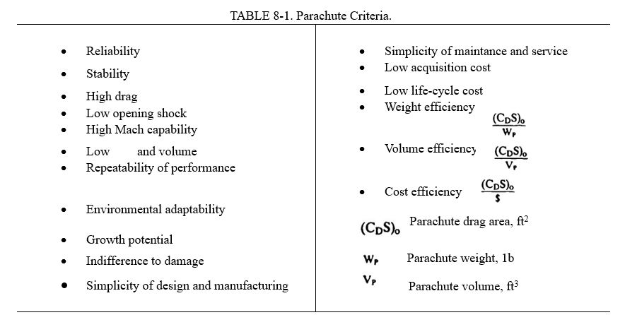
The figure demonstrates the known fact that airdropped bombs that explode on ground contact need larger decelerators than mines and torpedoes that are retarded primarily to avoid ricochet and damage at water entry.
Two types of inflatable aerodynamic decelerators are used as ordnance retarders: (1) parachutes of ribbon, ringslot, guide surface, and cross type design, and (2) inflatable balloon-type decelerators, called ballutes. Performance characteristics and design details of these two types of decelerators are discussed in Chapters 5 and 6. Textile retarders for ordnance devices are generally housed in metal containers that are part of the ordnance or are attached to the ordnance. Retarder deployment is accomplished by pyro or spring mechanisms that either eject the parachute directly or use a compartment cover that deploys the parachute or an intermediate pilot chute.
Textile retarders are stored individually or in tail housings in single or multiple containers, frequently hermetically sealed. Field or shipboard storage lives can be 10 to 20 years.
8.6.3 Bomb Retardation
The most important ballistic requirements for bomb retardation. especially for bombs dropped from low altitude at high subsonic and low supersonic velocities, are stabilization for obtaining a precise trajectory and sufficient separation between the aircraft and the exploding bomb.
Two typical bomb retardation systems are the parachute retardation assembly for the B-61 nuclear bomb and the ballute retarder system for the Air Force Mark 82 and Mark 84 and the Navy Mark 83 conventional bombs,
B-61 Parachute Retardation System. The B-61 nuclear ordnance device can be used alternately with a 17-foot-diameter, all nylon, conical ribbon parachute or with a hybrid nylon-Kevlar 24-foot-diameter conical ribbon parachute. Both parachutes have the same weight and fit into the same compartment. The 765-pound bomb has a final rate of descent of 75 ft/s with the 17-foot parachute, and 50 ft/s with the parachute. The 24-foot parachute uses Kevlar for suspension lines. radials. skirt, and vent tape. and for all vertical and some of the horizontal ribbons. The larger retarding force of the 24-foot parachute is a distinct advantage for high-speed, low altitude drops. Reference 5.42 and Reference 8.108 and Table 8-14 describe the development and list data on both parachute assemblies.
The B-61 parachute deployment system may be called a modified mortar ejection system (see section 6.1.9). The parachutes are packed in leaf-type cylindrical bags. split in the middle. and are pressure-packed with mechanical and corset-type lacing. The deployment bag has a cylindrical opening along its center for placing it around the telescoping ejector tube by means of two heavy webbing straps placed around the deployment bag. Upon ejection, the tube ruptures six shear pins that hold the rear cover in place and ejects the deployment bag by means of the pressure plate and the two heavy webbing straps. At full bag stretch, shear knives cut the bag lacing. An ejection velocity of 150 to 170 ft/s produces full suspension-line and canopy stretch. The two webbing straps and the pressure plate stay attached to the vent of the parachute.
A simpler deployment system. called in this manual a forced pilot chute ejection system, is used successfully on several other ordnance devices. A rear cover is pyro-ejected with several ejector bolts. The cover forms the vent of a pilot chute that in turn extracts the main parachute. Another tested version connects the ejected rear cover with several short straps to the deployment bag of a cluster of three ribbon pilot chutes that then deploy the main parachute. The cluster of three pilot chutes, that has been successfully tested up to low supersonic velocities, provides for a fast, uniform pilot chute action. This method is obviously simpler than the ejector tube method and eliminates the need for the center opening in the main-parachute deployment bag.
All parachutes used for ordnance retardation are manufactured to finished dimensions (see section 6.6.4). This assures that the parachutes will have a high degree of uniformity resulting in a precise, repeatable trajectory—an absolute necessity for dropping bombs with fully automated weapons management systems. References 5.41 to 5.47 describe the development of ribbon parachute assemblies used for ordnance retardation.
Mark 82-84 Ballute Retarder Systems. The Navy and the Air Force have developed ballute retarder assemblies for the Mark 82, 83, and 84 conventional bombs. The ballute retarder, frequently called an attached inflatable decelerator (AID) or a ram-air-inflated decelerator (RAID), is shown in Figure 8-29. The ballute inflates somewhat faster than a conventional parachute but requires more weight and volume for the same degree of retardation. All three bomb retarder systems have been tested up to low supersonic velocities and at altitudes as low as 100 feet References 8.109 to 8.111 describe the development of the ballute retarders for the Mark 82 and Mark 84 bombs. Deployment of the retarder is started by a steel cable lanyard attached to the aircraft. Upon lanyard stretch, spring-loaded clips that hold the rear cover in place are released. The rear cover is ejected and extracts the retarder. Four scoops around the periphery of the ballute inflate the Mark 83 retarder in 0.1 to 0.2 seconds.
Lifting Parachute Type Retarder. The Sandia National Laboratories have developed an interesting concept: A conical ribbon parachute is equipped with a lifting section consisting of horizontal ribbons with a high angle of attack This produces a lifting trajectory and results in a larger distance between bomb and aircraft for low-altitude bomb drops. Since parachutes are not stable in roll, a roll control system was developed consisting of a reference unit, a gas generator, and several exhaust nozzles that control bomb roll during lifting flight. The development of this concept is described in References 8.112 and 8.113.

8.6.4 Retardation of Aerial Mines
Aerial mines carried by fixed-wing or rotary-wing aircraft in underwing or fuselage installations require a low drag, somewhat streamlined shape, similar to torpedoes. Mines weigh from 500 to 2500 pounds and are being airdropped from to high altitudes at speeds from 50 to 500 knots.
Mine retarders must meet requirements similar to those for bomb retarders. The mine must be stabilized from drop to water impact and decelerated to 100 to 300 ft/s at stable water entry. The water entry velocity is governed by mine design, the operational concept, and the need to avoid damage at water entry. The water entry angle must be steep enough to prevent ricochet and broaching. One requirement is for precision mine drops into narrow water channels with sufficient aircraft-to-mine-impact distance to avoid inadvertently exploding mines.
Guide surface and ringslot parachutes are still used as retarders on older mines. Newer mine designs use the stable, low opening shock, cross parachute that is inexpensive and simple in design.
Mine retarder parachutes are usually housed in the tail fairing of the mine. These tail fairings are stored in hermetically sealed containers and are attached to the mine with channel-type metal bands consisting of three to four link-connected pieces.
The size of the retarder is determined by the weight of the mine and the allowable water entry velocity. The retarder must be disconnected at or slightly after water entry. The disconnect may be a mechanical device actuated by a paddle, or a pyrotechnical disconnect actuated by an impact deceleration sensor.
Textile retarders for mines have a shelf life of 20 years when stored in their hermetically sealed containers.
A typical parachute retarder for a 2400-pound mine has the following performance and design data: The retarder isa cross parachute with a surface area of S0 = 107 ft2, equivalent to a nominal parachute diameter of Do = 13.17 feet, and a drag area (CDS)p = 108 ft2, these parameters result in a ballistic coefficient of W/(CDS)p = 22.2 lb/ft2, and a water entry velocity of 137 ft/s. The parachute canopy material has a strength of 500 pounds per inch width, and the parachute has 24 suspension lines of 5500-pound strength each.
The parachute has been manufactured both in nylon and in all-Kevlar. The nylon parachute weighs 23.9 pounds. and the Kevlar parachute weighs 9.32 pounds, a weight saving of 61%. More detailed data on these two parachutes can be found in Reference 6.55. Both parachutes were tested at low and high altitudes at speeds up to 550 knots.
Figure 8-30 shows a typical mine cross parachute assembly in flight. Reference 8.114 describes the development of mine retarder parachutes by the Naval Surface Warfare Center at Silver Spring, Maryland, the primary Naval agency responsible for mine development. Reference 8.115 lists the military specifications for mine parachutes.

8.6.5 Stabilization and Retardation of Aerial Torpedoes
Aerial torpedoes weigh from 400 to 800 pounds, are dropped from 50 to 40,000 feet altitude and from zero up to high subsonic speeds, and enter the water at a velocity of from 50 to 200 ft/s. This lower water entry velocity, compared to mines reflects the less rugged torpedo design.
The aircraft drop procedure is similar to the drop procedure for bombs and mines: safe aircraft flight with the torpedo carried externally or internally and protected against premature deployment of the retarder; safe torpedo drop and separation from the aircraft; fast and reliable retarder deployment and inflation; and stable, predictable retarder descent until water impact and retarder disconnect. In some cases, water retardation is also required. Stable water entry at an angle of 30 to 60 degrees without nose cap, and 30 to 90 degrees with nose cap, is especially important to avoid ricochet or broaching and torpedo damage.
Guide surface, cross, and ribbon parachutes are used as retarders for various types of torpedoes. Reliable in-air and sometimes in-water performance of the retarder, timely separation, and long-term storage capability are prime retarder requirements. The operational modes and sensor systems of the torpedo affect the launch altitude and airspeed,
The retarder assembly is housed in a special container behind the propulsion section of the torpedo. The retarder disconnect may be of mechanical, pyrotechnical, or combined designs actuated by an impact inertia sensor. The retarder assembly is presently stored up to 20 years in a sealed storage container and attached to the torpedo prior to use.
A typical aerial torpedo retarder system has the following data:
Torpedo weight, 510 pounds
Water entry velocity, 150 ft/s
Retarder type ribbon parachute
Retarder diameter, Do = 7.5 feet
Number and strength of suspension lines, 12 lines, 3000 pounds each
Retarder drag areas, CDS = 22 ft2
Retarder ballistic coefficient, W/CDS = 23.6 lb/ft2
Deployment method, static line initiated
Parachute assembly weight, 20 pounds
Figure 8-31 shows a torpedo ribbon parachute retarder in flight.

8.6.6 Retardation of Illuminating Flares
Flares are used for battlefield illumination, aerial night photography, runway illumination for night landings, and similar applications. Gun-fired flares and aerial flares dropped from a variety of aircraft were used in large quantities in World War Il and in the Southeast Asia conflicts.
Flare shells are fired from 60-mm., 105-mm, and 155-mm guns, and from 81-mm mortars. A flare shell consists of the flare housing, the candle, the descent parachute assembly, and a mechanism that ejects candle and descent parachute at a preset time after firing or airdrop. The flare shell, at or after tiring from the gun, is subjected to accelerations of 10000 to 20000g, a deceleration that the flare shell assembly must be able to withstand, a high rotational acceleration, and candle and parachute ejection at shell rotations of 200 to 300 revolutions per second and shell speeds up to 2400ft/s.
Flare assemblies weigh from 2.4 pounds for the 60-mm flare shells to 50 pounds for airdropped flares. High drag. low oscillation parachutes are used for maximum descent time on the burning candle Slightly oscillating parachutes are claimed to provide a better resolution for target details. Solid material parachutes of special design arc usually used for feet for aerial flares. Steel cable and on steel cable suspension lines. of sufficient length arc used to protect the parachute the heat of the candle. The military agency responsible for flare development is the U.S. Army Armament Research, Development and Engineering Center at Piccatiny, NJ.
8.6.7 Sonar-buoy Deceleration
Sonar buoys are underwater listening devices that are dropped from rotary, and fixed-wing aircraft. After aircraft separation, stabilization and retardation of the buoy is necessary to achieve a predictable trajectory and an allowable water entry Sonar buoys range in weight from 12 to 39 pounds. Drop speeds vary from hover for helicopters to about 400 knots for modern antisubmarine warfare (ASW) aircraft, such as the Navy P-30 aircraft. The launch angle of the store relative to the aircraft is between 45 and 90 degrees, depending on the type of drop aircraft. Drop altitudes range from 30 feet for helicopter drops to 30,000 feet for patrol aircraft. The sensing equipment in the sonar buoys restricts the allowable water entry velocity to 120 ft/s and below.
A typical sonar buoy assembly is a tubular container 4.87 inches in diameter and 36 inches long. A parachute is housed in the rear of the tubular container. The store is ejected into the airstream by a pyrotechnic or pneumatic power source. A wind flap is mounted on the parachute end of the container. When the container enters the airstream, the wind flap is pulled away from the container, and, by means of a bridle between the wind flap and the parachute deployment bag, the wind flap extracts and sequentially deploys the suspension lines and the canopy, ensuring an orderly parachute inflation. The parachute opens in 0.1 to 0.15 seconds and stabilizes the store in 2 to 3 seconds. Equilibrium velocity of the store is reached in 10 to 12 seconds, followed by a stable descent to water impact. At water entry, the parachute is disconnected to avoid entanglement with the buoy.
A safety-of-flight requirement limits the length of the uninflated decelerator to 36 inches for all sonar-buoy configurations. A wind-tunnel and flight-test program was conducted with closely coupled cross, rectangular, and square parachutes of 1.5 to 5 ft2 of canopy area. The data obtained were used to define parachute designs that comply with a ballistic coefficient requirement of 18.0 + 1.5 lb/ft2 for stores between 32 and 39 pounds, and a ballistic coefficient of 12.3 ± 1.0 lb/ft2 for all other stores.
A slotted square parachute that meets all requirements is being produced. Development of this type of decelerator is continuing. References 8.116 to 8.120 describe development and test work on sonar-buoy parachute decelerator systems. Figure 8-32 shows a typical sonar-buoy parachute system. The U.S. Navy organization primarily responsible for sonar-buoy decelerator systems is the Naval Air Development Center, Air Vehicle and Crew Systems Development Department, in Warminster. Pa.

8.6.8 Retardation of Electronic Countermeasure (ECM) Jammers
ECM jammers are small electronic devices that block electrical signal propagation and return. Such jammers were used in great numbers in the Southeast Asia conflicts. These devices, weighing less than 10 pounds, are dropped from aircraft in dispenser-type containers and are ejected by centrifugal force or by pyrotechnic units.
Small parachutes of ballistic. gliding. or rotating design are used to provide maximum operating time at the desired altitude. Light weight, high drag, simplicity of design and manufacturing, and low cost are the prime requirements of these parachutes. These small parachutes are ideally suited for computer controlled, automated, mass production processes.
8.6.9 Shell Recovery
Malfunctioning fuses or components in gun or mortar-fired shells are impossible to inspect or analyze because they are destroyed at impact. It is desirable during the development and test phase to recover certain types of munitions for hardware inspection and functional analysis.
Parachute assemblies for the recovery of shells are subjected to the extreme environment of shell firing, with horizontal accelerations at firing of 10,000 to 20,00g, radial accelerations of up to 400,000 rad/s2, parachute deployment at shell velocities of 1000 to 2000 ft/s and shell rotation of up to 300 RPS. During firing, the high acceleration may result in a high hydrostatic pressure on parachute components and the parachute compartment.
The parachute usually is installed in the warhead at the tip of the shell. Parachute deployment, initiated by a shell fuse or timer, is accomplished by separating the warhead from the shell by pyro action. The parachute must stabilize the shell and decelerate it to ground impact velocities of 30 to 100 ft/s, depending on the sensitivity of the equipment to be recovered. The rotation of the shell during parachute deployment has caused system mutation before system stabilization. It has been found practical in some cases to use a steel-cable riser between parachute and shell, slightly longer than the shell, to avoid textile riser damage caused by contact with the tumbling shell section. A swivel between shell and riser is required to prevent riser and/or suspension-line wrap-up. Commercially available swivels frequently cannot handle the high loads and high RPS, necessitating the design of special swivels.
References 8.121 to 8.124 describe the development and testing of several shell-recovery systems, including such design details as swivels, steel-cable risers, and warhead separation methods. For long steel-cable risers, it may be practical to cast the wound steel cable in lightweight styrofoam to prevent cable twisting and kinking. This approach was used successfully on the long multiple-steel-cable risers of the Apollo drogue and main parachutes (Reference 5.10 and section 6.1.8), The type of parachute, number of parachutes, and parachute assembly layout depend on the type and weight of the munition to be recovered, the altitude and velocity at the start of the recovery, and the necessary impact velocity. As with most rocket and missile recovery systems. weight and volume of the parachute assembly is at a premium. Extensive use of high-strength Kevlar material and a high degree of pressure packing are recommended. Parachutes for this application seldom exceed 12 feet in diameter and may be considered one-time-use items not subjected to extreme environmental requirements.
8.6.10 Submunition Retardation by Parachute
Submunition refers to small cluster-type bomblets that are carried in airdroppable containers. After aircraft drop and a predetermined time, the container ejects the parachute-retarded bomblets.
The submunition may range from ballistic-parachute-retarded bomblets or mines to sophisticated, self-seeking, sensor fused, self-forging, fragment-type destructors descending on rotating, scanning parachutes with the capability to glide toward the target.
The submunition delivery system may be a simple, two-shell cylindrical container; a container with provisions for rearward or sideward ejection of the submunition in a preselected pattern; a winged vehicle with propulsion for a 10- to 20-mile standoff drop; or an engine-equipped, self-guided vehicle with a to 50mile range for attacking isolated military and supply concentrations. References 8.125 and 8.126 describe several such concepts.
Figure 8-33 shows a submunition delivery system. A standoff container, airdropped and retarded by parachute, lands and scans the area to find and identify suitable targets. Submunition is then rocketed toward the target, descends on a parachute in a scanning motion, flies toward the target, and explodes at a lethal distance. Such systems carry names like anti-armor cluster ammunition (AACA), extended range anti-armor mines (ERAM), and modular standoff weapon (MSOW).

Parachute requirements range from simple ballistic cross parachutes to a parachute that rotates and scans in a predetermined fashion. A considerable amount of theoretical and retarder hardware development work has been accomplished to define the operational characteristics and the dynamic behavior of rotating, scanning (conning), and gliding parachutes suitable for this application. This work includes a rotating guide surface parachute, the rotofoil, the vortex ring parachutes, and samara wing (maple leaf) type decelerators. The aerodynamic and inertia characteristics of the ammunition parachute system are frequently affected in a negative way by the wake of the forebody and gyroscopic forces.
References 8.127 to 8.134 describe theoretical and applied investigations of these types of retarders.
8.6.11 Radar Reflecting Target Parachutes
Specially designed parachutes have been used in the past as radar targets. These parachutes use silver, or aluminum-coated material in the canopy and arrange the material in a pattern that provides a desired radar return signal. An attempt was made to duplicate glint and scintillation of the radar return signals by parachute oscillation and/or rotation. Figure 8-34 shows the radar cross section of one of the parachutes investigated in References 8.135 and 8.136. Use of these parachutes was discontinued in the late 1960s when better radar targets became available.

In several recent applications, parachutes were equipped with a radar reflecting segment to enhance radar tracking References 8.135 and 8.136 provide information that is useful for this type of application. 8.7
8.7 PREMEDITATED PARACHUTE JUMPING
8.7.1 Scope of Application
Premeditated jumping with parachutes was first used in the 15th century in China and Siam, the parachutists jumped from high towers for show purposes.
The introduction of aerial balloons in the late 18th century in France instigated the competitive development of parachutes, first for saving the lives of balloonists in distress, followed by premeditated parachute jumps in air shows. Parachuting from balloons culminated around 1900 with the relatively modern parachutes and jump techniques of Tinny Broadwick in the United States and Kaethe Paulus in Germany (Reference 8.137).
The introduction and extensive use of military observation balloons in World War I necessitated the use of parachutes for escape from destroyed by enemy action. Parachutes were used for the recovery of balloons, gondolas. and personnel. Records indicate that balloon personnel emergency parachutes were also live tested for premeditated jumps.
The development and use of emergency escape parachutes for aircraft crew members started at the end of World War 1. The need to test parachutes to prove that they met the operational and performance requirements of the established specifications brought about the profession of the parachute test jumper.
Tie widest application of premeditated jumps and associated development of equipment and jump techniques when airborne military units were established to use parachutes for transporting troops to areas of military operations.
The U.S. Bureau of Land Management (BLM) and Forest Service use maneuverable parachutes for transportation of fire fighters (called "smoke jumpers") to remote fire areas. Also, maneuverable parachutes are widely used by the "sky divers"—sport jumpers.
8.7.2 Military Test Jumpers
At the end of World War when the development and use of emergency escape parachutes for aircraft crew members began, German pilots started using static-line-operated parachutes similar to parachutes used by military balloon observers (Reference 8.138).The first documented test jump using a manually operated freefall parachute was performed by Leslie Irvin, the founder of the Irvin Airchute Company, on 28 April 1919, at McCook Field in Dayton, Ohio. The parachute used was developed by a team headed by Major Hoffman. Floyd Smith was the chief parachute designer. The development of the parachute and the jump is described in Reference 8.139.
The introduction of high-performance aircraft during and after World War Il led to the development of ejection seats and crew escape modules. Parachutes developed for these new safety measures were (1) personnel emergency escape parachutes for individual aircraft escape. and (2) parachute systems to be used with ejection seats and crew modules. All parachute assemblies and parachute systems undergo extensive development and qualification tests, including live jumps by test jumpers. Ejection seats and crew modules and their parachute systems must permit emergency escape throughout the total aircraft flight performance envelope from zero velocity on the deck to maximum velocity and altitude, including such adverse flight conditions as aircraft being out of control, dives, spinning, etc. The personnel emergency escape parachute, as part of the ejection seat, is limited to deployment below 18,000 feet MSL and 250 KEAS.
Wilhelm Buss in Germany performed the first premeditated live ejection seat test in October 1941 from a Ju 87 bomber using a Heinkel-designed ejection seat (References 8.140 and 8.141). Bernard Lynch in June 1946 made the first live ejection seat test in Great Britain using a Martin-Baker-designed ejection seat (Reference 8.141), followed by Sgt. Larry Lambert who, in August 1946, at Wright Patterson AFB, ejected from a Northrop P-61 with a Wright-Field-designed seat (Reference 8.142). Warrant Officer E. Murray, in September 1959, made live ejection seat tests with the B-58 encapsulated seat, a small crew module.
The U.S. Navy, Army, and Air Force have test jumper units qualified to do live-jump tests of personnel parachutes. Testing emergency escape personnel parachutes involves developing aircraft exit procedures and testing extensive personnel rescue and survival equipment. Rescue and survival equipment may include pressure and temperature protective gear, emergency oxygen equipment, life rafts, emergency radio beacons, and related equipment fashioned for male and female aircrews, from the 5th percentile to the 98th percentile individual with a weight range from 150 to about 300 pounds.
The Naval Weapons Center at China Lake, Calif., has a fine-tuned program for training test parachutists. Training starts with a ground indoctrination program that acquaints the trainee with the equipment used. This training is followed by five static line jumps using paratrooper parachutes, a procedure that all military parachutists follow. The static-line jumps take place at Ft. Benning, Ga. The program continues with Phase 1 of a two-phase program at the Naval Weapons Center that includes 14 jumps with freefalls up to 15 seconds, using most of the Navy's personnel emergency escape parachute assemblies listed in Table 8-3 as well as the Army's MCI-IB (gliding T-10) and the aeroconical parachute used in the F-18 aircraft Martin Baker ejection seat.
During or after Phase 1 the trainee is introduced to the ram-air-inflated, maneuverable, gliding parafoil parachute in the "Parascension Program" (Reference 8.143). The trainee ascends from a towed launching platform on the inflated parafoil. During tow the trainee is instructed on the use of parachute controls and how to perform a landing. This has proven to be a safe, effective, and economic method of training parachutists and aircrew members in the use of high-performance, maneuverable parachutes.
In Phase 2 of the training program, the trainee is instructed in body control during long freefalls followed by gliding descent. Such maneuverable parachutes as the U.S. Army MC-3 (paracommander) and the MT-1XS/SL parafoil are used.
Table 8-15 contains information on maneuverable parachutes used by the U.S. military services.

Some of the parachute assemblies listed in Table 8-15 are used by military rescue and paramedics teams and by special forces of all services.
All of the listed parachute assemblies use parafoils as main and reserve parachutes. Figure 8-35 shows a typical parafoil in descent, ready to land with the jumper pulling full brakes. The design and the aerodynamic aspects of maneuverable parachutes in general and the parafoil in particular are discussed in section 5.9.

8.7.3 Paratroopers
In the early 1930s, the Soviet Union established the first airborne troops that were transported by aircraft to the war zone and dropped by parachute. In 1936, the German Air Force established an Airborne Division and began training paratroopers.
German airborne troops were used in the 1940 offensive against France and the low countries. Transported by gliders and dropped by parachutes, the troops overpowered a Belgian Fort and occupied some Dutch Rhine bridges. In 1941. the Germans dropped 8700 paratroopers on the Island of Crete. In 1943, the Germans introduced a modified Hoffman triangle gliding parachute. This parachute worked well in individual jumps, but in the first mass jump, fatalities occurred because paratroopers glided into each other and became entangled.
In the United States, the idea of dropping troops into military zones is credited to General Mitchell. In fact, to demonstrate the feasibility of this concept, a group of soldiers parachuted from the bomb bay of an aircraft.
U.S. and British paratrooper divisions, established at the beginning of World War Il, were used in the conquest of Italy, on D-Day in France, and later in an attempt to gain some of the bridges on the Rhine. Paratroopers also played an important part in the more recent invasions of Granada and Panama.
Paratroopers who jumped at Normandy found that the planned 700 jump altitude actually varied from 500 to 1500 feet because of the evasive maneuvers of the aircraft to avoid antiaircraft fire. Dropping troops from a 300 altitude is now the aim of military strategists to avoid radar detection and minimize the effect of antiaircraft fire.
Paratroopers carry ammunition, rifle, rockets, and other equipment, but the gear restricts the mobility of the paratrooper. The equipment and the low drop altitude leave little chance for maneuvering other than to obtain a favorable landing position.
During the invasion of Normandy in World War Il, U.S. paratroopers, because they used main parachutes with canopy-first deployment, used reserve parachutes. However, British paratroopers, who used main parachutes with lines-first deployment, used no reserve parachutes.
Paratrooper training consists of ground training, tower jumps, and five static-line jumps using the T-10 paratrooper parachute. Following this training. the paratrooper is ready for military airdrop operations. During the average enlistment of 3 to 4 years, a paratrooper may accumulate up to 35 jumps. Reserve parachutes are worn on all of these jumps.
A detailed discussion of the development, testing, and use of parachute assemblies for paratroopers can be found in section 8.4.8.
A distinct difference exists in the use of parachutes by paratroopers compared to parachute use by military test jumpers and sport parachutists. Where test jumpers use parachutes for investigation, and sport parachutists use parachutes for recreation, paratroopers use parachutes as a means of transportation from an aircraft to the landing area, uninjured and ready for action.
The U.S. Army is interested in developing a reliable, fast-opening, low-opening-force parachute that will lower a 390-pound paratrooper from an aircraft flying at 300 feet altitude at a rate of descent of 15 ft/s to a landing site 5000 feet above sea level. Low weight and volume must be considered when developing a new paratrooper parachute assembly.
8.7.4 Smoke Jumper Parachuting
The U.S. BLM and Forest Service use aircraft and parachutes to transport fire fighters to remote and inaccessible fire areas. In this case, Similar to the case of paratroopers, parachutes are used strictly as a means of reaching the fire area. In the past 10 years the BLM and Forest Service have changed to low rate of descent, highly maneuverable parachute assemblies.
Smoke jumpers carry equipment that can amount to as much as 80 pounds, bringing the average weight for the parachute to carry to about 250 pounds. The BLM Interagency Fire Center in Boise, Idaho, in conjunction with a parachute company, has developed a 330-ft2, seven-cell parafoil parachute that is similar in construction to the military MT1 ISS parafoil but differs in the method of deployment.
After the jumper exits the aircraft, a static line attached to the airplane deploys a large pilot chute. The pilot chute, attached to the jumper. decelerates and stabilizes the jumper. After a predetermined length of time, the jumper disconnects the pilot chute, and the pilot chute extracts and deploys the main parafoil. A kill line then deactivates the pilot chute.
The reserve parachute is a five-cell, 270-ft2 parafoil. This type of parafoil follows the trend in recent years of using a parafoil reserve with a parafoil main parachute.
The Forest Service Technology & Development Center in Missoula, Mont., has recently changed from the FS-10 (maneuverable T-10) to a newly developed parachute assembly, the FS-12. The FS-12 has an approximately round canopy 32 feet in diameter. This parachute uses low porosity material in front and high porosity material and openings in the rear to obtain glide, and Derry-type slots connected to control lines for maneuverability. The FS-12, when carrying a smokejumper weight of 250 pounds. has a measured rate of descent of 15.8 ft/s at MSL and a turn rate of 60 degrees/s.
The Forest Service and BLM have both developed sophisticated ground training programs including tower jumps, cable sliders for aircraft exit, parachute flight control, and a landing training mechanism with the jumper descending at a constant speed.
The Forest Service has a computer graphic maneuvering simulator for jump training. This simulator uses an IBM-compatible personal computer, software that permits variation in jump conditions and terrain, and a VCR and TV screen. The trainee goes through an entire jump, maneuver, and landing in typical forest-fire terrain. An instructor supervises and corrects the trainee's performance. This preliminary training is followed by ten to fifteen training jumps before actual fire jumps. Each year, smoke jumpers returning to fire duty make several training jumps and a proficiency jump every 14 days during periods of no fire fighting. Reserve parachutes are worn on all jumps.
Figure 8-36 shows a Forest Service smoke jumper wearing the FS-12 parachute assembly and standard jump gear.

8.7.5 Sport Parachuting
Sport parachuting started in the late 1920s in the Soviet Union and was sponsored by the government as paramilitary training for subsequent service as paratroopers. After World War Il, the French government established several sport parachuting centers that were followed by sport-jumping activities in several European countries and the United States.
Two developments helped to make parachuting a popular sport. The first was the development of sky-diving techniques in the early 1950s in France; the second was the invention in 1964 in the United States of the ram-air-inflated, maneuverable, hi-glide parafoil parachute by Domina Jalbert.
The sport parachute jump consists of two distinctly different phases. The first is a freefall phase where the parachutist, by body positioning and arm and leg movement, controls the freefall and performs glides, turns, loops, and other maneuvers. In the second phase, the jumper pulls the ripcord that opens the parachute pack and deploys the parachute. The parachutist then glides, turns, performs maneuvers. and prepares for and performs a spot landing.
Sky diving has grown so popular that it has become necessary to establish rules and regulations for the safety of the divers. The regulations encompass drop aircraft, sport parachuting centers, the training and licensing of instructors, jump masters, safety inspectors parachute riggers, and the use of the airspace. The U.S. Parachute Association (USPA) was formed by the sky divers and, in cooperation with the Federal Aviation Agency (FAA), establishes operational and safety regulations for sport parachuting.
Dan Poynter's book, Parachuting, and the Parachute Manual, References 8.137 and 2.22, describe all aspects of sky diving and parachuting, including the equipment used and the regulations that govern the sport.
In the 1950s and early 1960s, converted military parachutes, such as the standard 28-foot-diameter circular flat modified parachute with openings and slots for glide and turn control, were commonly used for sport parachuting. These parachutes obtained glide ratios of about 0.6 to 0.8 to 1. These were followed by the French LeMoigne and its offspring, the paracommander parachute shown in Figure 5-103. The paracommander has glide ratios of slightly better than 1 to 1. For a short time, versions of the Rogallo wing, shown in Figure 5-104 were used. The Rogallo wing produced glide ratios of up to 2.5 to 1. Parafoil parachutes are used almost exclusively now for sport parachuting.
Section 5.9 discusses the development and aerodynamics of maneuverable parachutes, all of which have certain technical aspects in common, such as the materials used and the means for obtaining glide and turn control.
Government agencies, including the military, have benefitted from the improvements in equipment and the training methods developed by the sport parachuting community. At first the assumption was that these high-performance, maneuverable parachutes would be difficult to operate and would require extensive training. Time and experience have overcome these problems. Advanced low porosity materials, new sewing techniques, pre stretched Dacron suspension lines, and lines manufactured with the super-strong Spectra material have greatly improved dimensional stability, decreased weight and volume, increased performance, and simplified the flying and control of high-performance parafoils.
The sport parachuting community calls the parafoil a ram-air-inflated, square parachute. This is a misnomer. All parachutes are ram-air inflated. Parafoils with a wingspan-to-wing-depth ratio of 2 to 3 are actually rectangular in wing planform, not square. The planform wing area of parafoils ranges from about 150 ft2 to more than 400 ft2, Parafoil canopies are manufactured from low porosity or nonporous fabrics. They behave aerodynamically, the same as rough surface, low-aspect-ratio aircraft wings. Wing loading as the ratio of jumper plus equipment weight divided by the area of the wing (W/S) affects the trajectory velocity of the aircraft. he same is true for parafoils—the higher the wing loading, the faster the forward velocity and the descent rate. The maneuverability is also greatly increased with higher wing loading.
High-wing-loading small canopies should be used only by experienced jumpers. Paratroopers and smoke jumpers (parachutists that use parafoils primarily as a means of transportation) use large, low-wing-loading parachutes that are slower in flight and landing, are easier to control, and are more forgiving of control errors.
Most parafoils use aspect ratios of 2 to 2.5. Higher aspect ratios result in more slender wings, lower wing drag, and better glide ratios. However, parachute deployment and control become more demanding. High-aspect-ratio parafoils, called parawings, are now being used for slope gliding and soaring in the manner of hang gliders.
Several methods are used to deploy parafoils and other maneuverable parachutes. Static-line deployment of the main parachute is used for student jumps with no freefalls. For freefall jumps, a manually or automatically deployed spring-loaded pilot chute is ejected into the airstream. After the pilot chute is inflated, it extracts and deploys the main parachute. Some parachutists prefer to hand-deploy an all-flexible pilot chute. The tandem parachute system uses a method similar to the smoke jumper method.
The nonporous canopy material used for the parafoil, and other hi-glide parachutes affects the opening behavior of the canopy. Wind-tunnel and aerial drop tests of low porosity or nonporous material canopies show that the canopy filling time is shorter than the filling time of standard porosity or slotted canopies. The shorter filling time results in about 50% higher opening forces than those of the standard material, round, flat canopies, and a 140% higher force than that of slotted canopies of ribbon or ringslot design.
To decrease the opening shock of parafoils, a slider is used. A slider is a rectangular piece of cloth with grommets on the four corners. The suspension lines are guided in four equally numbered groups through the grommets. The slider can thus move up and down on the suspension lines. When the parachute is deployed, the slider is up on the canopy keeping the canopy closed until line stretch occurs. This arrangement avoids a high snatch force (mass shock). The inflating canopy forces the slider down the suspension lines, controlling and slightly delaying canopy inflation to maintain a low opening force.
The left and right trailing edges of the parafoil are attached to control lines that a jumper can manipulate. Pulling down the left or right control line, thereby the left or right canopy trailing edge. increases the drag on the respective side and causes the parachute to turn in that direction. Pulling both control lines increases the drag as well as the lift of the canopy by increasing the airfoil curvature. This process, similar in action to aircraft flaps, is used during landing. The action of pulling both control lines is called "brakes." Half brakes may be used for the landing approach, and full brakes for landing. Reference 8.137 discusses in detail aircraft exit, freefall maneuvering, parachute glide, and landing.
The Basic Safety Regulations (BSR), published by the USPA and approved by the FAA. mandate the use of reserve parachutes for all sport parachuting. In the early days, round canopy parachutes of 22 to 26 feet in diameter were used as reserve parachutes, preferably the Navy 26-foot-diameter conical parachute. More recently, sport jumpers, the military, and the BLM fire fighters have used parafoil reserves whenever a parafoil main parachute is used.
Usually, a malfunctioning main parachute is disconnected (cut away) before the reserve parachute is deployed. An altitude controlled automatic activation device (AAD) is used by most parachute centers for reserve deployment during student training jumps. This automatic opener deploys the reserve parachute using a spring-loaded pilot chute. The AAD automatically deactivates if a pressure unit senses proper main parachute inflation. All reserve parachutes must be repacked every 120 days by an FAA certified parachute rigger.
Three training methods are in use for becoming a licensed sky diver: (1) the standard method, (2) the accelerated freefall method, and (3) the tandem jump method. The latter is frequently used in connection with the first two, usually as an introduction to sky diving.
The standard training method starts with ground training followed by five static line jumps. normally using a hi-glide parachute. The next steps are training in freefall, freefall maneuvers, parachute glide, and spot landing. After about 20 freefall jumps, the parachutist is eligible to apply for a USPA "A" license (Novice).
The sky diver, in subsequent jumps that include longer freefalls, more complex maneuvers, and precision landings, acquires USPA licenses B to D. These can be earned with a minimum of 200 jumps. Experienced sky divers perform freefall maneuvers forming stars and other formations with large numbers of sky divers participating. All these activities are sanctioned and supervised by the USPA, with strong emphasis on safety. The numerous awards available for extended freefalls, canopy relative work, and competitions are described in Chapter 9 of Reference 8.137.
The accelerated freefall method starts immediately with freefall jumps. The trainee is accompanied on the first jump by two certified jump instructors who advise the student on freefall body control, parachute deployment, parachute control, and landing. As the parachutist learns, the training changes to one accompanying instructor and then to unaccompanied freefalls.
Tandem Jumping. In the tandem training method, two persons freefall, descend, and land on the same parachute. An experienced parachutist, a rated "tandem master," is the parachute operator. A passenger is attached to the front of the instructor with four snaps and D-rings. This allows the passenger to enjoy a parachute jump, or a trainee to get the feel of freefall and operating and landing the parachute. Parafoils with 375 to 425 ft2 canopy area are used to obtain the same rate of descent as a single jumper. Tandem parachutes use hand-deployed large 52-inch-diameter pilot chutes that stabilize and decelerate the parachutists before the main parachute deploys. Manually disconnecting the pilot chute opens the parachute pack and deploys the main parachute. This tandem jump method is enjoying increased use for passenger jumping as well as for the accelerated training of sky divers. Reference 8.144 describes the tandem parachute concept.
Sport parachutists have developed three jump methods: the tandem jump method; BASE (buildings, antenna towers, spans (bridges), and earth (mountain cliffs)); and paragliding.
BASE Parachuting. Experienced parachutists jump from buildings, antenna towers, bridges, and mountain cliffs, all the locations inherent in the acronym, BASE. This type of parachuting requires a reliable, fast-opening, gliding canopy that opens away from the obstacle, often followed by a precision landing in a limited area. Canopies that open quickly at low deployment velocities and modified packing procedures have been developed from the sport of BASE parachuting. Reference 8.145 describes the sport of BASE parachuting.
Paragliding. Parafoil parachutes are used for gliding down steep slopes and in ridge and thermal soaring. When the slope of a hill is steeper than the glide ratio of a parachute, or the rate of descent of a parachute is slower than the updraft on a mountain ridge or a thermal, the parachute can be used for gliding and soaring. This activity is called paragliding.
High-performance gliders approach glide ratios of 50 to 1, hang gliders glide at up to 15 to 1. and parafoil paragliders now reach and surpass glide ratios of 5 to 1. This ratio is obtained through high-aspect-ratio wings; nine-cell canopies; better airfoils: and better airfoil shapes achieved by using plastic stiffeners, winglet type end cells, and other refinements. Parawings of this type are not suitable for sport parachuting because the paragliders lack maneuverability and have more critical stall characteristics (Reference 8.146).
Several technical innovations have been developed by the sky-diving community and associated industry. These innovations include the three-ring parachute disconnect; the canopy slider; the dual parachute pack; and excellent integration of harness, parachute pack, clothing. and related equipment.
8.8 REFERENCE MATERIAL
8.2 W. Knacke, "Report on the Work of the Parachute Department, Forschungsanstalt Graf Zeppelin." USAF translation F-SU-1107-ND, June 1946.
8.3 P R. Delurgio, B. A. Engstrom, and W. C. Buhler. "The Mid-Air Recovery System for the Air Launched Cruise Missile." AIAA Paper, October 1981. (AIAA 81-1915.)
8.4 W J. Everett and D. W, Henke, "Design & Development of a Light-Weight Mid-Air Retrieval Parachute System for Cruise Missiles," AIAA Paper, October 1981. (AIAA 81-1914.)
8.5 R. E. Runkle and W. R. Woodis. "Space Shuttle Solid Rocket Booster Decelerator Subsystems Drop Test 3—Anatomy of a Failure." AIAA Paper, March 1979. (AIAA 79-0431)
8.6 R. W Rodiet. "Reefing the Space Shuttle SRB-DSS Drogue Parachute." AIAA Paper, March 1979. (AIAA 79-0434.)
8.7 D. A. Kross and R. W. Webb. "Space Shuttle Solid Rocket Decelerator Subsystem Rocket Sled Test Program:' AIAA Paper, March 1979. (AIAA 79-0437,)
8.8 R. D. D. L. Bachus, and R, L. Utreja. "Performance Evaluation of Space Shuttle SRB Parachutes From Airdrops and Scaled Model Wind Tunnel Tests." AIAA Paper, March 1979. (AIAA 79-0464.)
8.9 R. E. Runkle and R. F. Drobnik. "Space Shuttle Solid Rocket Decelerator Subsystem-Airdrop Test Vehicle/B-52 Design." AIAA Paper, March 1979. (AIAA 79-046)
8.10 R. W. Rodier, R D. Moog, and D. R. Kross. "136-Foot Main Parachute for Recovery of Space Shuttle Solid Rocket AIAA Paper, April 1984. (AIAA 84-0804 CP.)
8.11 R. A. Corvin, W. R. and J. R. Reuter. "Design and Development of High Strength Parachute for Recovery of Filament Wound Case Space Shuttle Solid Booster." AIAA Paper. (AIAA 86-2432.)
8.12 U. S. Air Force. Compilation of Data on Crew Emergency Escape Systems, by J. O. Bull E, L. Senocki and H. L. McDonnell. USAF, September 1966. (USAF Report AFFDL.TR-66-150).
8.13 D. N. DeSimone. "Escape System Decelerator Technology." AIAA Paper, October 1981. (AIAA 81-1913.)
8.14 A. B. McDonald. "Ejection Seats in the Year Proceedings of the 16th Annual SAFE Symposium, San Diego, Calif., October 1978.
8.15 Naval Weapons Center. Conduct and Result of the GQ Type 1000 Aeroconical Parachute Assembly Qualification Program for Service Release in the NACES System, by F. H. Richards. China Lake, Calif., NWC. March 1988. (NWC TP 6906.)
8.16 T. Chadderton and J. S. Ungard. "Development of the 6.2-M Aeroconical Ejection Seat Parachute System." AIAA Paper. (AIAA 86-2454 CP.)
8.17 Naval Weapons Center. Aircrew Gliding Escape System (AGES) Exploratory Development Investigation of Aircrew' Emergency Escape Ram-lnflated Flexible Wing. by J. T. Matsuo and M. C. Butler. China Lake, Calif., September 1983. (NWC TP 6098.)
8.18 _____. In-Flight Ejection Seat Test Using the Aircrew Gliding Escape System (AGES) Parachute, by M. C. Butler. China Lake, Calif., NWC, September 1986. (NWC TP 6741.)
8.19 M. Herr. "Development of the Personal Parachute Assembly for the Space Shuttle Crew Escape System." AIAA Paper, April 1989. (AIAA 89-0922.)
8.20 R. Hauck. ''The New Crew Escape System, What Can it do for the Discovery Five?" Countdown, publication of the NASA Johnson Space Center. October 1988.
8.21 U. S. Air Force. Design Manual. USAF, February 1980. (USAF AFSC DH1-11.)
8.22 Military Standard. "Loading Environment and Related Requirements for Platform Rigged Airdrop Material." August 1968. (MIL.STD-669B.)
8.23 U. S. Army. Proceedings of Airdrop Systems, an Advanced Planning Briefing for Industry. USANRDEC, Natick, Mass., November 1988.
8.24 M. Gionfriddo. "U. S. Army Airdrop Technology Needs for the Future." AIAA Paper, November 1989. (AIAA 89-0977.)
8.25 U. S. Air Force. Evaluation of the C-130E Stability and Control Characteristics During Tandem, Sequential, and Single Platform LAPES Deliveries and Airdrop Deliveries, by E. L. Rutan and F. B. Stroup. USAF, November 1967. (USAF Report AFFTC-TR-67-18.)
8.26 _____. AC-130 Dual Rail Aerial Delivery System for Heavy Equipment Drop, by T. A. Olson. USAF, May 1962. (USAF Report AFTC-TR-62-17.)
8.27 U S. Air Force. Airdrop Tests of the XM-551 Army Full-Tracked Vehicle From a C-130 Aircraft, by R. P, Hastings. USAF, October 1964. (USAF Report AFTC-TR-64-30.)
8.28 U. S. Air Force. Development of a High-Speed, Low Altitude, Aerial Delivery Parachute System for Use With a Modified C-130 Aircraft, by E B. Morris. USAR December 1970. (USAF Report AFTC-TR-70-33.)
8.29 F. B. Stroup and E. L. Rutan. "Stability and Control During Heavy Weight. Low Level Cargo Delivery From a C-130E Aircraft." Society of Experimental Test Pilots. Technical Review, Vol. 8, No. 4. Pp. 1-2 1967.
8.30 U. S. Air Force. Performance Evaluation of a 25,000 to 35,000 Pound Capacity Extraction System for the C-141A Aircraft, by H. J. Hunter. USAF, August 1947. (USAF Report AFTC-TR-67-23.)
8.31 _____. C-141 Aircraft Aerial Delivery System, Category I Evaluation Tests, by H. J. Hunter. USAF. December 1966. (USAF Report AFTC-TR-66-32.)
8.32 U. S. Army. Joint Initial Operational Tests and Evaluation Developmental Check Tests of C-141 Container Delivery Systems. by J. P. Ford, et al. TECOM Project No. 4, April 1975. (Report 4-ES-065-000-001.)
8.33 U. S. Air Force. Evaluation Tests of C-5A Airplane Aerial Delivery System, Phase Il Airdrop and Jettison Capability, by H. J. Hunter and G. E. Boyer, USAF, November 1971. (USAF Report AFTC-TR-71-47.)
8.34 _____. Evaluation Tests of C-5A Airplane Aerial Delivery, Phase Ill, Modified Aerial Delivery System Components, by M. A. Tingdahi and H. J. Hunter. USAF. December 1972 (USAF Report AFTC-TR-72-52.)
8.35 _____. Cargo Handling System A/A32H4, by M. A. Tingdahi. USAF, February 1964. (USAF Report AFTC-TR-63-46.)
8.36 _____. Evaluation of A/32H-4 Dual Rail Cargo Handling System for Airdrop and Low Level Cargo Delivery, by R. J, Ducote. USAF, December 1964. (USAF Report AFTC-TR-67-35)
8.37 _____. Advanced Weather Aerial Delivery System, by B. D. Ferrier. USAF, November 1971. (USAF Report TAC Test 70A-037A (AD 889 197L).)
8.38 _____. Pendulum Release Parachute Extraction System (PREPS), by P. A. Dehmer, USAF. June 1969. (USAF Report TAC Test 68-224 (AD 853 569L))
8.39. _____. 463L Universal Cargo Handling System, by T. A. Olson. August 1962. (USAF Report AFTC-TR-62-27.)
8.40 B. C Bonaceto and J. F. Schroeder, "Aircraft Controlled Exit System (ACES)." AIAA Paper. October 1984. (AIAA 84-0821.)
8.41 U. S. Air Force. Development and Evaluation of a C-130 Aircraft Low Altitude Parachute Extraction System (LAPES) for Aerial Delivery of Single and Tandem Cargo Platforms at Ground Proximity, by C O. Laine. USAF, March 1968. (USAF Report AFTC-TR-68-3)
8.42 _____. Comparison Study of the Ground Proximity Extraction System and the Low Altitude Parachute Extraction System (LAPES) as Method of Tactical Aerial Delivery of Combat Forces, by J. W, Worley and D R. Hughes. USAF, August 1969. (Air Force Institute of Technology Report SLSR-40-69.)
8.43 _____. Joint Tests of 1528 LAPES, Phase 1, by R. W Hink. USAF June 1973. (TAC Project 72B.203T.)
8.44 _____. Joint Tests of 1528 L4PES, Phase 11, by W. Foss. USAF, September 1973. (TAC Project 73TB-102X,)
8.45 _____. Low Altitude Aerial Delivery (Fighter Aircraft). Results of Qualification Testing of the M-4A Modified Container Aerial Delivery System, by P. L. Weintraub. USAF, November 1966. (USAF Report AFTC-TR-66-36.)
8.46 _____. Development of a High Speed, Low Altitude Aerial Delivery System for Use With a Modified C-130 Aircraft, by E B. Morris. USAF, November 1970. (USAF Report AFTC-TR-70-33.)
8.47 _____. High Speed, Low Level Aerial Delivery System (HSLLADS), by I. L Franklin. USAF. March 1974. (TAC Project 73A-079T)
8.48 _____. Evaluation of a Radar and Barometric Altimeter Activated Two-Stage Airdrop System, by M. J. Wuest. USAF, August 1975. (USAF Report AFFTC-TR-75-25.)
8.49 _____. Military Potential Tests of Interim High Level Container Airdrop System (HLCADS), by E. J. Barnicle. USAF. August 1975. (USAF Report ASD-TR-74-23.)
8.50 _____. Feasibility Investigation of a Two-Stage Platform Mounted Airdrop System, by J. Krizauskas. USAF, July 1975. (USAF Report AFFTC-TR-75-22.)
8.51 _____. Development and Evaluation of a Two-Stage, High Altitude Airdrop Container System, by W, N. Massey and J. Krizauskas, et al. USAF, November 1974. (USAF Report AFFTTC-TR-74-32.)
8.52 _____. G. A. Barnard. "Development of a High Level Airdrop Container System," AIAA Paper. November 1975. (AIAA 75-1386)
8.53 _____. W B. Pepper, et al. "Adaptation of a 15-foot-diameter Ribbon Parachute and a 73-Foot Cross Main Recovery Parachute for Cargo Delivery From High Altitude." AIAA Paper. (AIAA 84-0790.)
8.54 _____. U. S. Air Force 150-Foot-Diameter Straight Gore, Solid Flat Parachute, by C. R. Graham. USAF, February 1954. (USAF FTL-54-16 (AD 289 123).)
8.55 _____. Bibliography of 6511th Test Squadron (Parachute) Technical Publications 1952-1975, by W H. Packard. USAF, January 1976. (USAF Report AFFTC-TI-76-1.)
8.56 _____. Acceptance Tests of G-13 Parachutes, by R. H. Rice. USAF. January 1954. (USAF Report AFTC-TN-53-7.)
8.57 _____. G-13, 500-Pound Cargo Parachute, by C R. Graham, USAF, August 1954. (USAF Report FTC-LR-54-20.)
8.58 _____. G-12B, 64-Foot cargo Parachute Cluster Tests, by C W. Marshall. USAF. March 1958, (USAF Report AFTC-LR-58-102.)
8.59 _____. G-11A Parachute Ultimate Drop Test Conditions, by C. R. Graham. USAF, September 1954. (USAF Report FTC-TN-54-23.)
8.60 _____. Evaluation Tests of C-5A Airplane Aerial Delivery System, Phase Il, Airdrop and Jettison Capability, by J. B. Hunter and J. E. Boyer. USAF, November 1971. (USAF Report AFFTC-TR-71-43.)
8.61 U. S. Army. Development Tests 11 (Service Phase) of G-11A Vent Control System for Division Ready Force (DRF), by K. T Cooksley. TECOM Project No. 4, April 1975. (Report 4-ES-60-011-005 (ADV 003 848).)
8.62 _____. A Discussion of the Applicability of Parachutes With Pull Down Vent Lines for Airdrops of Supplies and Equipment From a 500-Foot Altitude, by E. J. Giebutowski. USA, October 1971. (Report 72-23-(ADV 750-585),)
8.63 U, S. Air Force. Internal Parachute Study, Phase Il (Clusters), by M. A. Tingdahl. USAF, May 1967. (USAF Report FTC-TM-67-109 (AD 289 123).)
8.64 W. J. Everett, E D. Vickery, and R. A. Vernet. "Recovery of 60,000 Pounds Using a Cluster of Six 137-Foot.Diameter Parachutes." AIAA Paper, March 1964. (AIAA 84-0800 CP.)
8.65 E. D. Vickery, M. L. Eldridge, and R. A. Vernet. "Development of a System of Six Clustered 137-Foot-Diameter Parachutes to Recover 60,000 Pounds," ALAA Paper, October 1986. (AIAA 86-2445)
8.66 U. S. Air Force. Development of a Parachute System for Minuteman 1 Missile Launched From a C-5 Aircraft, by C W. Marshall, et al. USAF, April 1975. (USAF Report AFFTC-TR-75-2.)
8.67 U. S. Army. Porotype Cluster Parachute System for a Unit Load of 50,000 Pounds, Volumes I and II by R. A. Toni. ANLABS. (Report NLABS.TR-69-83-AD.)
8.68 H. J. Hunter, "An Airdrop System for listing Large Parachutes for Recovery of Loads in Excess of Pounds." AIAA Paper, May 1973. (AIAA 72-471.)
8.69 U. S. Air Force. A Study of Design and Materials for Low Cost Aerial Delivery Parachutes. USAF, September 1959. (USAF Report WAD-TR-59-385.)
8.70 _____. A Study of Design and Materials for Low Cost Aerial Delivery Parachutes, by F.A. Ruprecht. USAF, June 1962. (USAF Report ASD-TDR-62-309.)
8.71 U. S. Army. Letter of Report of Engineering Design Tests (Airdrops) of the "-Pound-Capacity Plastic Film Low Cost Parachute. TECOM Project No. 4, November (Report 4-5-7498-02.)
8.72 U. S. Air Force. The Criteria for Non-Standard Airdrop Loads. USAF, December 1977. (USAF Report AFD-TM-ENE-77-1.)
8.73 _____. Extraction Systems, by C. W. Marshall. USAF. July 1958. (USAF Report AFFTC-TR-58-6.)
8.74 _____. Extraction Parachute Clustering Techniques, by C. W Marshall. USAF, October 1958. (USAF Report AFTC-TM-58-18.)
8.75 _____. 35-Foot Ringslot Parachute Extraction System Development, by Hi J. Hunter and R. P. Hastings. USAF July 1964. (USAF Report FTC-TR-64-17.)
8.76 _____. Performance Evaluation of a Cluster of Two 28-Foot Do Ringslot Extraction Parachutes Towed From a C-130 Aircraft. USAF, August 1965. (USAF Report FTC-TR-65-25.)
8.77 _____. Performance Evaluation of Heavy Duty 28-Foot Do Ringslot Extraction Parachute, by F. B. Morris. USAF, December 1968. (USAF Report AFFTC-TR-69-43.)
8.78 _____. Development, Test and Evaluation of an Extraction Parachute Subsystem for Airdrop From the C-5A Aircraft, by J. M. Black. USAF, October 1969. (USAF Report AFFTC-TR-69-29.)
8.79 U. S. Army. A Parachute Retrorocket Recovery System for Airdrop of Heavy Loads, by G. A. Chakoian. USANLABS, November 1969. (USANLABS-TR-70-34AD.)
8.80 _____. Final Engineering Report-Parachute Retrorocket Airdrop System, by J. L. Michal, et al. USA, December 1970. (USA Report TR-72-16(AD736 361).)
8.81 U. S. Army. An Active Optical Ground Sensor for a Parachute Retrorocket Airdrop System, by R. R. Ulrich and A. J. D'onofrio. USA, February 1973. (USA Report HDL-TM-73-2.)
8.82 _____. Plan for Advanced Development o/a Parachute Retrorocket Airdrop System, by G. A. Chakoian. USA, October 1972. (USA Report TR-73-59-AD.)
8.83 J. D. Cyrus. "Retrorocket-Assisted Parachute In-Flight Delivery (RAPID) System Development Update." AlAA Paper. (AIAA 86-2465-CP.)
8.84 U. S. Air Force, "The Precision Drop Glider (PDG)." By J. E. Forehand, U.S. Army. Paper presented at the Symposium on Parachute Technology and Evaluation, El Centro, Calif., USAF, April 1969. (USAF Report FTC-TR-64-12, pp. 34-44.)
8.85 Sandia National Laboratories. Controlled Recovery of Payloads at Large Gliding Distances Using the Parafoil, by C.P Knapp and W. R. Batron, SNL, November 1967. (SNL Report SC-R-67-1049.)
8.86 U. S. Air Force. Parafoil Steerable Parachute Exploratory Development for Airdrop System Applications, by R. J. Speelman. USAF, April 1972. (USAF Report AFFDL-TR-71-347.)
8.87 Sandia National Laboratories. A Study of Gliding Parachutes for Accurate Cargo Delivery, by W. B Pepper. SNL July 1971. (SNL Report SC-TM-72-0298.)
8.88 E. Puskas. "The development of a 10,000-pound-capacity Ram Air Parachute." AIAA Paper, April 1989. (AIAA 89-0904)
8.89 R. T Mayer. "Terminal Descent Controlled Vehicle Recovery." AIAA Paper, April 1989. AIAA 84-0801.)
8.90 R. T Mayer, E. Puskas, and P. Lissaman, "Controlled Terminal Descent of Large Aerospace Components." AIAA Paper, (AIAA 86-2467 CP.)
8.91 U. S, Army. Product Improvement Test (Service Phase) of T-10 Personnel Parachute (Modified With 3- and 3/4-inch Mesh Net), by K. P. Foster. TECOM Project No. 8-EG-0, March 1975. (Report 8-EG-060-010-003(ADB 004 284L).)
8.92 A. J. Fallon and J. W. Watkins. "The Annular Parachute—an Approach to a Low Altitude Personnel Parachute." AIAA Paper. (AIAA 86-2449-CP.)
8.93 U. S. Air Force. Quick Opening Reserve Parachutes, by M. B. Kanowski. USAF, July 1959. (USAF Report AFFTC-TN-59-10.)
8.94 U. S. Air Force. Amy Troop Reserve Parachute, Ballistically Deployed Pilot Chute, by C O. Laine. USAF, March 1963. (USAF Report FTC-TR-63-4.)
8.95 U. S. Air Force. Performance Evaluation of a Gas-Deployed Reserve Parachute, by R. B Calkins. USAF, April 1971. (USAF Report FTC-TDR-71-10.)
8.96 U. S. Army. Check Test of Reserve Parachute Personnel, Troop Chest, Ballistically Deployed, by D. E. Wolstenholme and T. Dolighan. USA, November 1971. (Report AB 1470-2 (AD 892 431L).)
8.97 U. S. Air Force. Steerable Parachutes, by D. Gold and J. Rosenberg. USAF, January 1955. (USAF Report FTC-TN-55-1.)
8.98 Naval Weapons Center. Performance Evaluation 35-Foot Diameter Extended Skirt Maneuverable Personnel Parachute, by G. R. C. Menard. China Lake, Calif., NWC, April 1967. (NWC TR-8-66.)
8.99 U. S. Army. Service Tests of Maneuverable Troop Back Personnel Parachute, Modified, by B. R. Franklin. TECOM Project No. 8, March 1970. (Report 8-EG-065-000-001 (AD868 721L).)
8.100 U. S. Air Force. Performance Evaluation of Para-Commander Mark I Personnel Parachute. by C. W. Nichols. (USAF Report FTC-TR-66-16.)
8.101 H. J. Hunter and M. J. Wuestt, "Aerial Delivery of Personnel in Ground Proximity." AIAA Paper. (AIAA 89-0887-CP.)
8.102 U. S. Air Force, Low Level Multiple Personnel Delivery Capsule, by J. O. Deering. USAF, October 1966. (USAF Report SEG-TR-66-10 (AD 880 624))
8.103 _____. Concept for a Multiple Personnel Airdrop System, by J. E Falcone. USAF. November 1973. (USAF Report FTC-TR-74-15-AD (AD 771 945).)
8.104 Military Specification. "Parachutes." MIL-P-87141A. November 1986.
8.105 U S. Air Force. B-47 Approach Control Parachute, by J.W. Kiker. USAF, July 1954. (USAF Report ARDC-TN-WCLE-54-18.)
8.106 National Aeronautics and Space Administration. Summary of Design Considerations for Airplane Spin-Recovery Parachute Systems, by M. B. Sanger. Jr. NASA. August 1972. (NASA Report NASA-TN-D-6866.)
8.107 H. P. Stough. "A Summary of Spin-Recovery Parachute Experience on Light Airplanes." AIAA Paper, 1990. (AIAA 90-1317-CP).
8.108 W. B. Pepper, "Design and Development of a 24-Foot Diameter Hybrid Kevlar/Nylon Parachute," AIAA Journal of Aircraft, Vol. 17, pp 45 to 52, January 1980.
8.109 P. G. McGirr and A. C. Aebisher. "Development and Testing of Ballute Stabilizer/Decelerator for Aircraft Delivery of a 500-Pound Munition. " AIAA Paper, May 1973. (AIAA 73-485.)
8.110 U. S. Air Force. Evaluation of a Ballute Retarder System for the Mark-82 Bomb, by R. A. Evors. USAF, May 1973. (USAF Report ADTC-TR-73-31.)
8.111 _____. Preliminary Investigation for Applying a Ram-Air Inflatable Decelerator (RAID) as the Retardation System for the 800-Pound Modular Bomb—Summary Report, by M. C. Miller. USAF, February 1974. (USAF Report EC-TR-73052.)
8.112 W. B. Pepper and J. R. Bistervbold. "An Omnidirectional Gliding Ribbon Parachute and Control System." AIAA Paper, May 1973. (AIAA 73-486.)
8.113 R. E. Rychnowski. "A Lifting Parachute for Very-Low-Altitude, Very-High-Speed Deliveries." AIAA Journal of Aircraft, Vol. 14, No. 2, February 1977.
8.114 Naval Surface Warfare Center. Some Highlights of the United States Naval Surface Weapons Center-White Oak in the Field of Retardation Systems, by W. P. Ludtke. White Oak, Md., NSWC, October 1982. (NSWC-MP-82-446.)
8.115 Military Specification. "Parachutes for Underwater Mines." MIL-P-21904A(OS), March 1987.
8.116 C. T. Caliano. “Aeroballistic Characteristics of a Sonarbuoy Parachute Limited to a Length of Three Feet." AIAA Paper, October 1981. (AIAA 81-1950.)
8.117 Naval Air Development Center. AN/SSQ-41, Two Stage Parachute System, by E. A. Reed, III. Johnsville, Pa., NADC, October 1972. (NADC-72174-VT.)
8.118 _____. AN/SSQ-41A/53 Sonardrop Q41 System Qualification Tests Q53 Developmental Tests, by E. R. Gombos and E. A. Reed, Ill. Johnsville, Pa., NADC, December 1972. (NADC-72209-VT.)
8.119 _____. Sonarbuoy Effective Drag Area Ballistic Coefficient, and Parachute Construction Requirements. Sonarbuoy Production Document, Johnsville, Pa., NADC, 15 April 1988. NADC SPD-13C.)
8.120 C. T. Caliano. "Drag and Stability Improvements of a Square Parachute." ALAA Paper, October 1986. (AIAA 86-2471.)
8.121 Sandia National Laboratories. Parachute System to Recovery of A Spinning (250 RPS) 155-mm Shell Subjected to 20,000 gs Launch Condition, by W. B. Pepper and R. D. Fellerhoff. SNL, September 1968. (SNL Report SC-R-68-1806.)
8.122 D. E. Waye, C. W. Peterson, and W. T. Botner. "Design and Performance of a Parachute Recovery System to Recover 155-mm and 8-inch Diameter Artillery Shells." AIAA Paper. (AIA.A 86-2444.)
8.123 C. A. Moehler and D. W. Pillasch. "Development of a Two-Stage Projectile Payload Deceleration System." AIAA Paper. (AIAA 86-2443 CP.)
8.124 J. A. Buckley. "Missile Recovery System for High-Speed Small-Caliber Missiles." AIAA Paper, October 1986. (AIAA 86-2462.)
8.125 S. K Ibrahim. "An Overview of Munition Decelerator Technology With Recent Applications at Honeywell." AIAA Paper, May 1984. (AIAA 84-0780.)
8.126 H. Wanstell. "Flying Dispensers for Stand-Off Attack." Interavia Aerospace Review, July 1989, Pp.717 to 720.
8.127 R. J. Kingsley and J. Reuter. "Development of a Lifting Parachute to Provide Self-Dispersing Capability for an AVCO Designed Tactical Ammunition." AIAA Paper, October 1981. (AIAA 81-1928.)
8.128 R. Kline and W. Koenig. "Samara Type Decelerator." AIAA Paper, April 1984. (AIAA 84-0807.)
8.129 D. W. Pillash, J. C. Shen, and N. Valero. "Parachute/Submunition Coupled Dynamics." AIAA Paper, April 1984. (AL 84-0784.)
8.130 P. Crimi. "Analytical Modelling of a Samara-Wing Decelerator." AIAA Paper. October 1986. (AIAA 86-2439.)
8.131 Z. Shpund and D. Levin. "Improved Measurements of the Dynamic Loads Acting on Rotating Parachutes." AIAA Paper. October 1986. (AIAA 86-2473.)
8.132 K F. Doherr and R. Synofzik. "Investigation of Rotating Parachutes for Submunition." AIAA Paper, October 1986. (AIAA 86-2438.)
8.133 J. Reiff. "Parachute Studies Conducted at MRB, Aeromechanical Two-Body Model With Nine Degrees of Freedom." Paper presented at the University of Minnesota/CarI Cranz Gesellschaft Lecture on "Parachute Technology: Fundamentals, Concepts and Applications," Munich-Oberpfaffenhofen, July 1987.
8.134 W. H. Koening "A Flexible Fin Deployment Simulation." AIAA Paper, April 1989. (AIAA 89-0919.)
8.135 Hughes Aircraft co. Missile Target Systems Pogo-Hi, Vol. 4, by H. K. Eppie. HAC, January 1960. (Report TM603.)
8.136 University of Texas. Reflecting Characteristics of Pogo Parachute Models D556, D503, and P/B 509-330, by C. O. Britt, L. C. Kraus, and W. W. Bahn. UT Electrical Engineering Research Laboratory, January 1960. (Report EERL 3-24.)
8.137 D. F. Poynter, Parachuting. Book published by Para Publishing, P. O. Box 4232. Santa Barbara, Calif., 93140. Fifth edition, 1989.
8.138 T. W. Knacke. "Technical-Historical Development of Parachutes and Their Applications Since WWI." AIAA Paper, October 1986. (AIAA 86-2423.)
8.139 P. Hearn. Sky High Irvin. Book published by Robert Hale Limited, Clerkenwell House, Clerkenwell Green, London ECIR OHT, 1983.
8.140 S. Ruff, M. Ruck, and G. Sedlmayr. Sicherheit and Rettung in der Luftfahrt. Bernhard Graefe Verlag, Karl-Mand Strasse 2, 5400 Koblenz, West Germany, 1989.
8.141 Bryan Philpott. Eject, Eject, Ian Allan Ltd. Publishers, London. Sole U.S. distributor: Motorbook International, Osceola, WIS. 54020, 1989.
8.142 U. S. Army Air Force. Human Subject Ejection Test From a P-61 Airplane, by H. Fouch. USAAFMC, August 1946. (Report No. TSEAC-45341-2-1.)
8.143 Naval Weapons Center. Parascension Training Program, by M. C. Butler and M. A. Peltz. China Lake, Calif., NWC, September 1986. (NWC TP 6728.)
8.144 B. Booth. "Tandem Jumping." AIAA Paper. (AIAA 86-2485-CP.)
8.145 J. Boenish. "BASEic Sport Parachuting; We Will Cross (Jump Off) That Bridge When We Come to lt." AIAA Paper. (AIAA 86-2484-CP.)
8.146 M. J. Ravnitzky. “Today's Slope Soaring Technology Previews the Future of Advanced Ram-Air Canopies for Parachutists." Skydiving, Vol. 9, No. 10, Issue 106, April 1990).