Parachute Design
CHAPTER 6
DESIGN OF PARACHUTE ASSEMBLY AND COMPONENTS
The prime contractor, generally in cooperation with a government agency or other customer, defines the load, personnel, ordnance, and air or space vehicle that must be recovered. The prime contractor specifies the vehicle weight and configuration, the recovery velocity and altitude envelope, the landing conditions, and the environment in which the recovery system must operate.
The recovery system contractor, usually a subcontractor, develops and tests the parachute system and, if required, the impact-attenuation system. The components of this task may range from a single parachute assembly for parachutists to a multiple parachute assembly for the recovery of a space vehicle.
The systems analyst, the systems engineer. and the aerodynamicist then define the required recovery system that may include a drogue chute and main parachute assembly, an impact-attenuation system, and other components. They define the type and number of parachutes required, and the necessary reefing stages, as well as the installation, deployment, and recovery signal method. These tasks should all be done in close cooperation with the prime contractor. The design engineer then converts the calculated data into reliable, workable hardware that will meet the recovery specification.
The parachute design engineer must learn to design in textiles, the primary material of parachute assemblies. Textile fabrics are subject to the same laws of stress and strain as metals or composites. However, many differences exist in the nonlinear elastic characteristics of natural and man-made fibers that are woven and braided into cloth, tapes, and suspension lines and are then connected by sewing to form parachute assemblies.
6.1 PARACHUTE DEPLOYMENT AND INSTALLATION
6.1.1 Parachute Deployment
Parachute deployment denotes the sequence of events that begins with the opening of a parachute compartment or parachute pack attached to the body to be recovered. Deployment continues with extraction of the parachute until the canopy and suspension lines are stretched behind the body and the parachute canopy is ready to start the inflation process. This deployment is associated with a mass shock (snatch force) created by the acceleration of the mass of the parachute to the velocity of the body to be recovered. The task of a good deployment system is to limit the mass shock to an acceptable level. Shock limitation is accomplished by controlling the parachute deployment process and providing means for progressive incremental acceleration of all parts of the parachute to the velocity of the forebody. A high snatch force is usually the result of a poor deployment system. The need for a controlled, progressive parachute deployment increases with parachute size and deployment velocity, and with the number of parachutes in the assembly. An uncontrolled high acceleration of the canopy skirt may also cause reefing cutters to rip away from their anchor points and damage the reefing installation.
A good parachute deployment system provides the following benefits:
1. Minimizes the parachute snatch force by controlling incrementally the deployment of the parachute, and by keeping the parachute canopy closed until line stretch occurs. Acceleration of the air mass in a partially inflated canopy before line stretch is a main contributing factor to high snatch loads.
2. Keeps tension on all parts of the deploying parachute. Tension prevents fluttering of the canopy. Fluttering causes entanglement, canopy damage, line-overs, and canopy inversions.
3. Minimizes opening time and opening-force scatter caused by irregularities and delayed action during parachute deployment and inflation.
4. Supports uniform deployment and subsequent inflation of parachute clusters. This is of utmost importance in clusters to avoid wide discrepancies in forces and opening times of the various parachutes. Design approaches for preventing these problems are discussed in section 6.3.1.
Means for obtaining a good, controlled parachute deployment include a positive method for parachute extraction by a mechanically or pyro-ejected pilot or drogue chute. Aerodynamically deployed spring-loaded pilot chutes, used successfully for personnel parachutes, are generally not satisfactory for deployment of large final descent parachutes for air vehicles and ordnance devices.
Parachute and riser should be stored in a textile envelope for protection during deployment and to ensure a controlled deployment that keeps tension on all parts of the parachute and riser. This textile envelope, called the deployment bag, should have separate compartments for the canopy, suspension lines and, if required, for the riser. These components should be secured in their individual compartments in sequential steps (folds) in stow loops or retention ties, so that the pull of a pilot or drogue chute first extracts the main parachute from the parachute compartment and then from the deployment bag in a controlled incremental sequence, thereby maintaining order and tension on all parts of the deploying parachute assembly.
Questionable deployment methods should be avoided or thoroughly tested. Bench deployment tests are an essential part of the design-and-development cycle. During the bench test, the engineer should try to make the deployment system malfunction. If the system does malfunction in bench tests, the same malfunction will certainly occur sometime when the parachute is being used; the malfunctioning part should be redesigned.
6.1.2 Uncontrolled Deployment
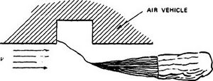
In an uncontrolled deployment, the parachute is released or ejected into the airstream without a pilot chute, drogue chute, or deployment bag (Figure 6-1). Uncontrolled deployment may be acceptable for small parachutes less than 5 feet in diameter but is unacceptable for larger parachutes because it results in high snatch forces and partial canopy inflation before line stretch. If tension on the canopy and lines is not controlled, line-overs, inversions, entanglement between parts of the parachute, and parachute damage can occur.
6.1.3 Semi-controlled Deployment
Semi-controlled deployment uses a pilot chute for extracting the main parachute (Figure 6-2).
The semi-controlled concept has worked with medium-sized parachutes deployed at low velocities. If deployment occurs over a large velocity range, the pilot chute may be powerful enough at high speeds to cause high snatch loads, and not powerful enough at low speeds to avoid sail formation. Partial canopy inflation before canopy stretch may still occur with this deployment. Use of a deployment bag is a better solution for pilot chute deployment.

6.1.4 Static Une Deployment
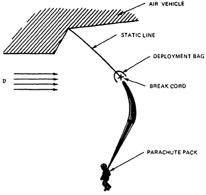
In the static-line-deployment method, a line attached on one side to the air vehicle and on the other side to the parachute assembly will first open the parachute pack and then pull the parachute out of its deployment bag. A typical example is the T-10 paratrooper parachute used by the airborne troops of many western nations. The static-line deployment of the T-10 parachute is shown in Figure 6-3. After the jumper leaves the aircraft, a static line attached to the aircraft opens the parachute pack attached to the back of the paratrooper, extracts the parachute stowed in a bag attached to the static line, and deploys the parachute. The static line with the attached deployment bag stays with the aircraft. This parachute extraction method is limited to aircraft speeds of about 130 knots. Above 130 knots, sail formation will occur because the parachute is deployed at 90 degrees to the airflow, which pushes the front of the canopy skirt through the rear of the skirt and results in partial or full canopy inversion. Inversions on the T-10 parachute have been practically eliminated through introduction of the anti-inversion net around the skirt of the canopy (see section 6.3.4 for a description of the anti-inversion net).
Many variations of the static-line-deployment method have been used in operational systems. A related approach was used for deployment of the stabilization and retardation parachute for the nose section of the XS-2 research aircraft. In case of an emergency, explosive bolts were used to separate the nose section, which contained the pilot cockpit, from the aircraft. A static line attached to the aircraft fuselage extracted the drogue chute deployment bag and deployed the parachute. This system performed well in a high-speed emergency (Reference 5.11). However, a static-line-deployment method must be carefully analyzed to determine its suitability for the intended application. The controlled-deployment method described in the next paragraph is often a better approach.
6.1.5 Controlled Deployment
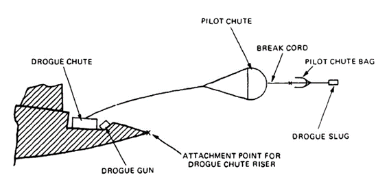
The controlled parachute deployment method, shown in conceptual form in Figure 6-4, is the basic deployment method for all parachute assemblies used for the recovery and retardation of air/space vehicles, ordnance items, and high-speed payloads. This method is also recommended, in an appropriate form, for other parachute assemblies, including personnel and aircrew emergency parachute systems.
Controlled parachute deployment starts with the forced ejection of a parachute compartment cover or a drogue gun slug that, in turn, pulls a pilot chute or first-stage drogue chute, away from the air vehicle and into airflow behind the vehicle. Mortar ejection or rocket extraction may also be used for forced deployment of pilot or drogue chutes.

Figure 6-4 shows a controlled deployment of a parachute assembly that starts with ejection of the compartment covert which extracts the pilot chute stored in a small bag. Important in the deployment of the parachute assembly is the sequence: riser, suspension lines, and canopy. This type of sequence is called line-first deployment. The deployment bag of the main parachute contains two compartments, one for riser and suspension lines, and another for the canopy. All assembly components are retained in their respective compartments, using stow loops and tie cords. This arrangement ensures a controlled deployment with tension on all parts of the parachute assembly.
Figure 6-4 shows the pilot chute permanently attached to the main parachute canopy, an arrangement that has proven beneficial to all large, reefed parachutes.
Mortar ejection or rocket extraction deploys the pilot or drogue chute directly. These methods are described later.
Main parachutes are sometimes too large for forced deployment by mortar or rocket action. An intermediate, force-deployed pilot chute or the disconnected drogue chute are used for extracting very large main parachute assemblies.
6.1.6 Canopy-First Deployment
The canopy-first deployment method (Figure 6-5) should be avoided wherever possible: it results in high snatch forces and associated problems. This method had to be used on the landing deceleration parachute of the B-47 bomber to prevent the parachute deployment bag from falling and being dragged on the runway. The parachute deployment bag was permanently attached to the riser at a distance short enough to prevent the bag from contacting the ground. A large pilot chute extracted the canopy from the bag in a canopy-first process. The airflow around the canopy prevented dragging the canopy on the ground.

6.1.7 Drogue Gun Deployment
A positive ejection of the pilot chute or first-stage drogue chute, as provided by a drogue gun, mortar, or extraction rocket, is mandatory whenever the parachute must be deployed from a spinning or tumbling vehicle or through the wake of a large forebody. Drogue gun deployment, the simplest of the three forced-ejection methods, is shown in Figure 6-6.
A drogue gun is similar in principle to a pistol. The gun body is attached to the primary vehicle. At deployment command, a piston, similar to the pistol shell, and called a drogue gun slug, is fired away and beyond the reach of the tumbling vehicle into good airflow behind the vehicle. The drogue gun slug attached to a bridle either extracts the pilot chute directly or extracts a small deployment bag containing the pilot chute.
Drogue gun slugs are limited in weight to about 2 pounds, restricting their use to lightweight pilot chutes. Drogue guns, which have a low reaction force, can be stowed conveniently at various locations on the primary vehicle. Figure 6-6 shows the drogue gun slug permanently attached to the pilot chute bag, with slug and bag breaking away after deployment is complete. This design is preferred because it prevents the drogue gun slug from becoming entangled with and damaging the pilot chute.
6.1.8 Parachute Mortar Deployment
If drogue gun deployment can be compared to firing a pistol, mortar deployment can be compared to firing a shell from a cannon. Drogue chute and main parachute assemblies in excess of 100 pounds have been mortar-deployed. Mortar deployment is a very positive means of getting a parachute assembly away from the effective range of a spinning or tumbling vehicle and into good airflow behind the vehicle. The disadvantages of mortar deployment are a large mortar reaction force; a relatively large mortar body; and a canopy deployment, not by the pull of a pilot or drogue chute, but by the inertia forces of the ejection. A large ejection velocity is required to accomplish bag strip-off and line and canopy stretch.
Figure 6-7 shows the mortar arrangement for the two Apollo drogue chutes. The Apollo command module was unstable and could rotate 90 degrees between the time the stabilization system was shut off and the time the drogue chutes could stabilize the command module. Contact between the red-hot heat shield and the drogue chute risers appeared possible. Firing the drogue chutes at 90 degrees to each other ensured that one drogue chute would be effective at all module attitudes. In addition, high-temperature-resistant steel cables were used in the contact range of the heat shield. Note that only one drogue chute was required for the primary landing system; the second drogue was part of the backup assembly.
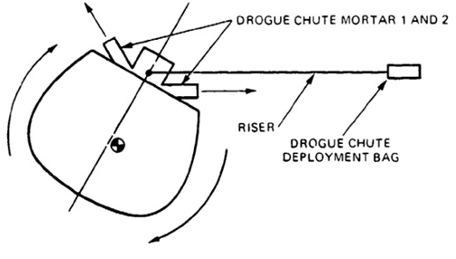
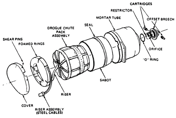
Figure 6-8 shows the mortar assembly for the Apollo drogue chutes. The drogue chute is contained in a deployment bag stowed in a sabot (piston). The mortar tube has two cartridges firing into a common volume actuated from two individual sensor systems. Upon deployment command, both cartridges are fired. This firing builds up the pressure below the sabot, transmits the pressure to the cover, shears the pins holding the cover, and ejects the deployment bag and riser assembly. For the Apollo drogue chutes, the multiple steel cable risers were wound into a ring without turning the cables and were held in place by casting them in lightweight Styrofoam.
Static firings of the mortar confirmed bag strip-off and canopy stretch. Mortar cover, sabot, and the lightweight Styrofoam were lost after ejection. No interference between the parts and the drogue chutes was found. The high mortar-reaction loads were somewhat controlled by proper breech and orifice design (Reference 5.10). A variety of mortar concepts and designs have been used operationally. Reference 6.1 analyzes the design and performance of a parachute mortar.
6.1.9 Deployment by Rocket Extraction
Figure 6-9 shows two typical rocket-extraction methods. Version 1 stows the rocket beside the parachute assembly, and version 2 stows the rocket in the middle of the doughnut-shaped deployment bag. Both versions have been used successfully. Rocket extraction provides favorable deployment by pulling the parachute bag from the top and providing a line-first deployment sequence. Rocket extraction creates no reaction forces that must be absorbed by the vehicle. Protection against the short-time rocket blast has not been a problem. References 6.2 and 6.3 describe several rocket-extraction systems.

6.1.10 Crosswind Deployment
Deployment bags that are stowed within cavities in air vehicles need a means for ejecting the deployment bag assembly into the airstream. Three methods that have been used operationally are shown in Figure 6-10. All three concepts require careful evaluation in bench deployment tests.
A frequent problem with air vehicle installation of parachute assemblies is a vertical stabilizer in the path of the deploying parachute assembly. One successful method for solving this problem is described in Reference 5.23.

6.1.11 Parachute Assembly Installation
Parachute assemblies must be stowed inside or on top of the air vehicle or the payload that the parachute is to retard or recover. The shape of the stowage area or compartment for the parachute assembly should ensure favorable storage and deployment conditions for reliable parachute operation. The recovery-system engineer should get involved in the vehicle or payload design so that an acceptable compartment or stowage location and an unobstructed deployment path for the parachute can be obtained. Although parachute assemblies can be stowed in the last left-over hole in the aircraft or missile, odd compartment locations may require complex and expensive parachute ejection or extraction systems, difficult deployment concepts, and higher than necessary localized pack densities.
Airdrop platforms and airdrop equipment normally permit the parachute assembly to be located on top of the load, with sufficient space for hand-packed parachutes that have not been pressure-packed, and in a location that provides an unobstructed path for parachute deployment into good airflow.
Cylindrical or aerodynamically shaped slender vehicles. such as ordnance items, missiles, rockets, and aircraft, generally permit storage of the parachute assembly, or part of the assembly, in a compartment at the rear of the vehicle. However, this installation requires that the parachute be ejected from the container four to six forebody diameters behind the vehicle, through the reverse flow region into good airflow, to ensure proper canopy inflation.
Many missiles, target drones, and aircrew modules require a horizontal vehicle attitude for ground landing and an angled attitude for water landing. Most vehicle recovery systems require a drogue chute for high-speed deceleration and a main parachute assembly for final descent. Available vehicle space dictates stowage of the main parachute on the upper or lower side of the vehicle; the upper side is the preferred location. During descent on the drogue chute, the vehicle must be in a nose-down, minimum-drag attitude to avoid pendular and transverse oscillations. Vehicle rotation during drogue-chute descent, caused by ailerons not in zero position, can twist the risers and lead to squidding of the parachute. A swivel between the drogue chute and the vehicle may be necessary to prevent tangling. The drogue chute can deploy the main parachute by using a transfer bridle located in an indented channel in the vehicle skin, covered by a fly-away strip of material. The main parachute may also be deployed independently of the drogue chute by using one of the deployment methods previously discussed.
To avoid damage to the parachute assembly during installation and deployment, the parachute-stowage compartment must be smooth on the inside with no protrusions or sharp edges. If rough edges (such as those caused by compartment covers cut out by a detonating fuse cord) cannot be avoided, a plastic or textile inner liner may be used to cover the rough edges.
The deployment path of the parachute outside of the vehicle should be free of protrusions and obstacles, such as vertical fins. If anything is in the deployment path that the parachute can hang up on, the parachute will certainly do so at some time.
Most parachute compartments in air vehicles are rectangular, and, because space is limited, require pressure-packing of the parachute. Pressure-packing of parachutes into noncylindrical deployment bags requires the special knowledge and handling discussed in section 6.7.5.
Operational use has shown that it is practical to have removable parachute compartments. This arrangement allows parachute handling, packing, and installation in packing lofts to be away from other work on the vehicle, and provides ready-packed parachutes for quick turnaround as well as easy storage and protection of the parachutes under hostile environmental conditions.
Landing a vehicle in a stable horizontal or angled attitude requires three riser attach points, preferably two in front of and one behind the center of gravity of the vehicle. These hard points must be so arranged as not to interfere with parachute installation or deployment.
A very important but frequently overlooked point is the provision for parachute growth. Historically, air vehicles, crew modules, and payloads have grown in weight. The Apollo command module from its bidding specification to its first landing grew from 8,100 to 13,000 pounds with no permissible increase in parachute storage, volume, or parachute loads. This weight increase has made extremely dense pressure-packing and multiple reefing stages necessary for all parachutes.
The permissible maximum landing velocity is usually based on the allowable impact deceleration. To accommodate a higher vehicle weight without increasing the rate of descent requires a larger parachute with even more dense pressure-packing. A limit exists as to how much pressure-packing a parachute can withstand without damage to the parachute and its components.
The following design details must not be overlooked:
- Missiles, rockets. and drones that are accelerated on launchers in fractions of a second from zero velocity to flying speed press the parachute assembly with considerable force against the rear cover or door, necessitating proper design of the door restraint.
- In cylindrical containers, parachute suspension lines that are attached at multiple points in the front end of the container easily chafe at the rear edge of the container. A wide webbing ring attached to all suspension lines at the rear location eliminates this problem.
- Disconnecting the parachutes from the vehicle at landing is frequently necessary to avoid wind dragging. Pyro disconnects of various designs are available and in use. Sensors for initiating these devices include ground-impact and contact switches for ground landing, and impact and water-activated switches for water landing. It is important to activate the sensor circuitry only after all parachutes are open and the system is stabilized. This avoids disconnecting the parachutes by door ejection, parachute forces, and similar shock or electrical-signal sources.
Two interesting parachute installations in air vehicles. one with a 180-degree vehicle tip-over and the other with a vertical stabilizer in the parachute deployment path, are described in References 5.23 and 6.4.
Insisting on a good parachute installation and a clear parachute deployment path will pay multiple dividends in a more reliable parachute recovery system.
6.2 PARACHUTE DESIGN
6.2.1 Parachute Assembly Configuration
Parachutes constitute the primary elements of parachute recovery systems. These systems range from single parachutes used for the recovery of small loads at low speeds to multiple parachute systems for the recovery and landing of heavy military loads. ordnance devices, and air vehicles.
Recovery from velocities below 150 to 200 knots can generally be accomplished with a parachute assembly consisting of one or several main descent parachutes deployed by static line or by aerodynamically deployed pilot chutes.
Recovery from velocities in excess of 200 knots, as a rule, requires a multiple-parachute system where the individual parachutes may be reefed in one or several steps. Such systems may include pilot chutes, first- and second-stage drogue chutes, and final descent parachutes that may be supported by ground-impact-attenuation systems.
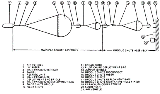
Figure 6-11 shows a typical parachute recovery system that consists of a drogue-chute assembly and a main parachute assembly. The drogue chute, mortar-deployed in a deployment bag, is attached to the vehicle by a pyrotechnically actuated disconnect. A sequencer controls the firing of the disconnect and the release of the drogue chute. Upon drogue-chute disconnect, a jumper bridle extracts the pilot chute for the main parachute. After extraction of the pilot chute, the drogue chute with the attached pilot chute bag breaks away. The permanently attached pilot chute now deploys the main parachute, which is reefed in one or several steps. Depending on the type of vehicle to be recovered, a swivel and a transfer bridle may be required, the swivel to prevent a rotating forebody from twisting the main parachute, and the transfer bridle to shift the vehicle into a horizontal attitude for ground landing.
6.2.2 Parachute and Component Definition
Figures 6-12 to 6-14 show the components of a parachute labeled with generally accepted terminology. The two primary components of a parachute are the canopy and the suspension lines. The parachute canopy is the drag-producing component that provides the decelerating force. This force is guided through suspension lines to a riser that connects the parachute to the payload or air vehicle. Some payloads, such as cylindrical ordnance devices, connect the suspension lines, without a riser, directly to the vehicle. All circular parachute canopies are designed with more-or-less-triangular gores manufactured of sections cut from woven parachute cloth. The formerly 36-inch-wide parachute cloth is presently being replaced with cloth 48, 60 and 72 inches wide. Parachute cloth is available in a variety of weaves with strengths from about 40 to 500 pounds per inch-width.
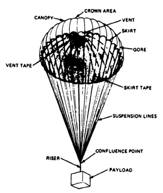
Figure 6-13 shows details of a flat circular canopy. The layout, numbering system, and general definitions are in accordance with MIL-P-85710. The gores are numbered in a clockwise direction when viewed from the top of the canopy in the direction of flight. The gore with the highest number has in the right-hand corner above the gore number a decal containing such data as drawing number, date of manufacture, and contract number.
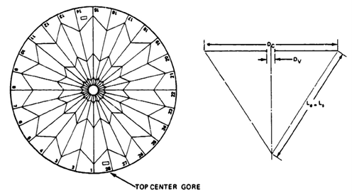
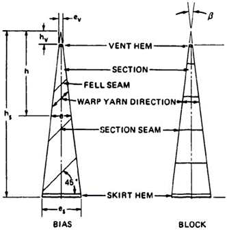
Figure 6-14 shows two gore layouts with the sections cut in bias and block construction. Bias cut provides better stress distribution in the canopy and equalizes unavoidable small differences in manufacturing; this is the preferred construction method. Block construction, although simpler to design and manufacture, is primarily used for low-speed, low-load parachutes.
The individual gore sections are generally connected with a two-needle, 1/2.inch French fell seam with a 3/8-inch needle gage. A more efficient method uses a 3/8-inch fell seam with a 1/4-inch needle gage.
Most older parachutes use a 1-inch-wide, 4-needle fell radial seam to connect the individual gores to the suspension lines that run through a channel formed by a gap between the second and third rows of stitching. Many other radial-seam designs are in use today. One method runs the suspension lines on top of the radials over the canopy. Another has narrow radial seams with tapes sewn on top of the radials; the suspension lines are connected to the canopy skirt by sewing them to the tapes or running them through loops formed by the radials at the skirt of the canopy. Care must be taken to secure the suspension-line radial connection against side pull of the lines during deployment. Specification MIL-C-6635C, the ribbon parachute specification, shows several methods of connecting the suspension lines to the canopy skirt. Later sections of this chapter describe the design of the most commonly used parachute types and give references and specifications that describe the design of specific parachutes.
6.2.3 Design of Solid Material Parachutes
Flat Circular and Conical Circular Parachutes. The flat circular parachute is the patriarch of all parachute designs and is still used for personnel and cargo-type parachutes, such as the 28-foot-diameter C-9 personnel parachute, and the 64-foot-diameter G-12 and 100-foot-diameter G-11 cargo parachutes. The flat circular parachute is simple to design, manufacture, and maintain, and has proven very reliable in operation. References 5.13 through 5.20, 5.95, 6.5, and 6.6 describe design and testing of circular flat parachutes of various diameters and for various applications.
Tests have established that conical and quarter-spherical parachute canopies, for the same canopy surface area, have a higher drag than flat parachutes (Reference 5.1). These results led to the design of conical parachute canopies; the best-known design is the Navy 26-foot-diameter conical parachute. References 6.7 and 6.8 describe conical parachutes.
Figure 6-15 shows the design and the nomenclature used for circular flat and circular conical parachutes. On flat parachutes, the canopy cone angle, u, is zero and the gore angle, y, is 30 degrees divided by NG.
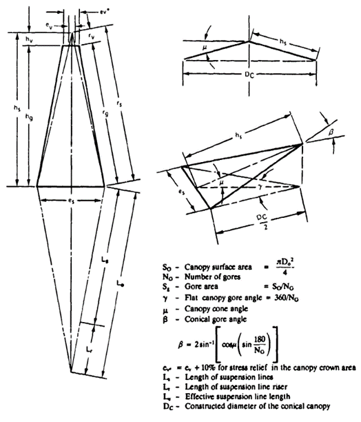
Section 6.4.5 discusses the benefits of relieving stress in the canopy by extending the calculated width of the gore, ev. by 10% to ev*
For large parachutes with long suspension lines, it has been proven practical to gather several lines in a single riser. This arrangement prevents length differences in the suspension lines that can be caused by differences in the elongation of adjacent lines. The effective suspension-line length, Le, is always the distance from the skirt of the canopy to the real or hypothetical confluence point of the suspension lines.
Extended-Skirt Parachutes. Schematic drawings of three types of extended-skirt parachutes are shown in Figure 6-16: (a) the 10% extended-skirt designs, (b) the full (14.3%) extended skirt. and (c) the conical full extended skirt. The center part of the 10% extended-skirt designs is flat. Added to the skirt of the parachute is an inverted flat fabric ring with a width of 10% of the canopy diameter. The first extended-skirt parachute was a 28-foot-diameter circular flat parachute with 10% of the outer part of another 28•foot canopy sewn to the original canopy. The best-known example of this type is the T-10 paratrooper parachute. A 12.5% flat extended-skirt parachute was tested at Wright Field. It was more stable than the 10% canopy but was slow to inflate and tended to delay opening.
The full extended skirt, flat and conical parachutes, designs (b) and (c) shown in Figure 6-16, have a 14.3% skirt extension. The angle of the extension coincides with the angle formed by the suspension lines. The conical full extended design has a conical center part; this design provides the highest drag coefficient of the three types.
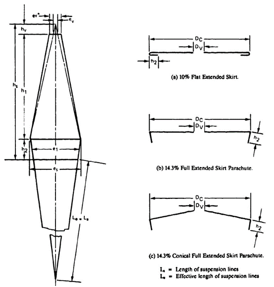
Figure 6-16. Design of Extended-Skirt Parachutes
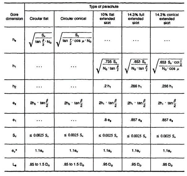
Figure 6-16 shows the design and the nomenclature, and Table 6-1 shows the dimensions for the different extended-skirt types.
The suspension-line length on the extended-skirt parachutes is usually equivalent to 0.95 to 1.0 diameter. Lengthening the suspension lines beyond Le/Do 1.0 provides little gain in drag because the skirt extensions restrict the growth of the inflated-canopy diameter. This is contrary to flat circular and conical canopies, where longer lines notably increase the parachute drag (see Figure 5-20). For design details on extended-skirt parachutes, see References 5.21 through 5.24.
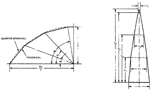
Polyconical Parachutes. Polyconical parachutes are a design modification of the high-drag quarter-spherical canopy discussed in section 5.2. Figure 5-16 shows the increased drag of this parachute compared to the circular flat parachute. The canopy profile is varied in a series of straight-line segments along a quarter-spherical arc. The triconical shape is the most commonly used design. Figure 6-17 shows the closeness of the quarter-spherical and triconical gore shapes. The number and length of the individual straight-cut gore sections can easily be varied to avoid material waste during manufacturing. Material waste is a problem on shaped-curvature gore designs.
The gore dimensions shown in Figure 6-17 are typical. No generally accepted standard designs have evolved. All companies that are designing polyconical parachutes have developed their own gore designs.
Cross Parachutes. Cross parachutes, also called cruciform parachutes, were developed in the late 1940s by the Naval Ordnance Laboratory in Silver Spring, Md. Cross parachutes have had considerable use in recent years for the landing deceleration of aircraft, for stopping dragster racing cars, and for the retardation and stabilization of ordnance.
Figure 6-18 shows the simple design that consists of two layers of material connected in cross form. Drag, stability, and opening force are affected by the ratio of arm width, W, to arm length, L, A lower W/L ratio produces better stability and a lower opening-force coefficient, Cx: however, a lower W/L ratio also produces a lower drag coefficient, CDo. References 5.25 through 5.35. 6.9, and 6.10 give design and aerodynamic information.
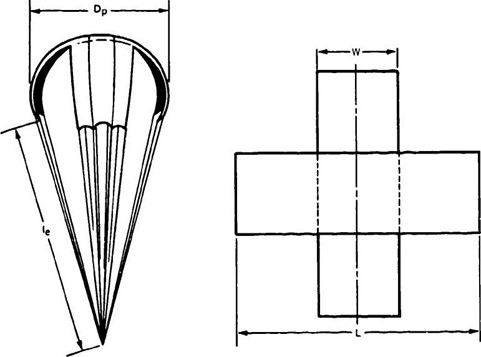
Cross parachutes have a tendency to rotate. Rotation can be diminished by connecting adjacent arm corners with a restricting line long enough to permit full canopy inflation but not long enough to permit overinflation. Parachutes used for the deceleration of dragsters frequently form the ends of the four arms into a pocket for faster canopy inflation. References 5.28 and 5.29 show that suspension-line length and number of suspension lines have a notable effect on the drag of cross parachutes.
Annular Parachute. The annular parachute, whose performance is discussed in section 5.2, evolved from the airfoil parachute and may be described as a conical parachute with a large pulled-down vent and with lines attached to the outer suspension lines (Reference 5.36). Figure 6-19, taken from Reference 5.36, demonstrates the design of the airfoil parachute.
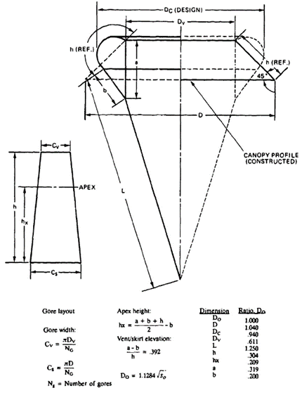
Annular parachutes are used for midair retrieval with an engagement parachute attached above the open vent of the annular parachute, as shown in Figure 5-6 and described in References 5.37 and 5.38. A U.S. Army application is discussed in Reference 6.11.
Of all known parachute types. the annular and the polyconical parachutes have the highest drag coefficients related to the canopy surface area. Changing the relationship of the dimensions a and b in Figure 6-19 will notably affect the parachute performance.
Guide Surface Parachute. Two types of guide surface parachutes are in use, the ribbed guide surface and the ribless guide surface. Both parachute types have a dome-shaped, rounded crown and an inverted cone-type guide surface in front of the dome. The guide surface causes uniform flow separation around the canopy edge and provides a strong restoring moment if the canopy is moved from the zero-angle attack position. Low-porosity canopy material is used for obtaining a fast, uniform inflation. Guide surface parachutes have the highest stability but the lowest drag of all known parachute types.
Ribbed Guide Surface Parachute. The ribbed guide surface parachute is the older type. It has a steeper dcm/dc slope than the ribless type but it is more difficult to manufacture and has a slightly higher weight and volume. Figure 6-20 shows the general design of the ribbed guide surface parachute. References 5.53 and 6.12 detail design of two variations of the ribbed type of parachute, a stabilization type (the design shown in Figure 6-20), and a brake type with shorter guide surfaces.
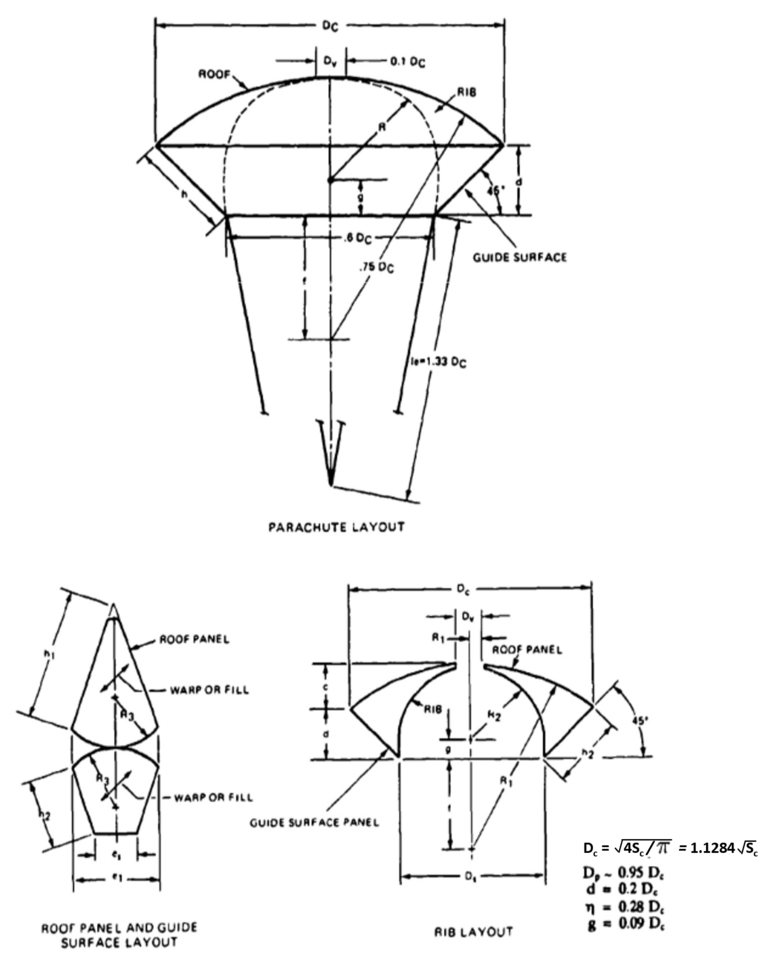
Guide surface parachutes, unlike most other parachute types, use the constructed parachute diameter, DC. and the related canopy area, Sp. as reference for the drag coefficient CDp.
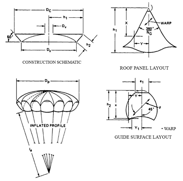
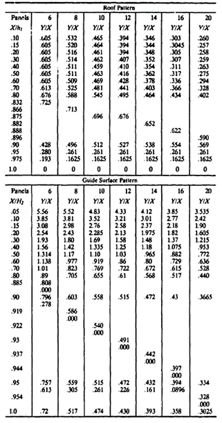
Ribless Guide Surface Parachute. The ribless guide surface parachute eliminates the rib by extending the gore panel around the edges of the guide surface. Extending the gore creates more rounded corners on the guide surface and fewer sharp separation edges, resulting in a slightly lower dcm/dα slope. A vent in the outer pocket of each gore ensures good inflation. Roof and guide surface dimensions vary with the number of gores. Figure 6-21 shows the general design. Panel dimensions for the various gore designs are listed in Table 6-2 taken from Reference 2.1. Additional design and performance data are found in References 5.53 and 5.54. Reference 5.54, a British report, gives slightly different panel dimensions but includes parachutes with more gores.
6.14 Design of Slotted Parachutes
The slotted parachute family started with the design of the flat ribbon parachute, frequently called the FIST ribbon parachute after the Flugtechnisches Institute at T. H. Stuttgart where the parachute was developed in the late 1930s. In the late 1940s, the conical ribbon parachute was introduced at Wright Field; this parachute had, for the same canopy surface area, a 10% higher drag than the flat canopy parachute (Reference 5.1). In 1949, Knacke and Hegele developed the ringslot parachute as a supplement to the ribbon parachute. The ringslot parachute, surprisingly, had a 10 to 15% higher drag than the ribbon parachute but the same stability and opening-force coefficient CX. The ringslot parachute has found wide application as a landing deceleration parachute for aircraft and as an extraction parachute for airdrop platforms.
In 1955, Ewing modified the ringslot parachute by changing its canopy shape and detail design. The resulting ringsail parachute had a larger drag and a shorter filling time. but also a slightly reduced stability.
An Air Force research program for the investigation of supersonic parachutes developed the hemisflo ribbon, the hyperflo, and the parasonic parachute. These parachutes proved to be superior to the conical ribbon parachute for longer application in the above-Mach 1.5 supersonic range.
Other slotted parachutes include the disk-gap-band parachute used for the Viking lander on Mars, and the square slot parachute.
Flat and Conical Ribbon Parachutes. The ribbon parachute was developed as a parachute suitable for the in-flight and landing deceleration of aircraft and missiles. It has good stability and a lower opening force than the solid flat circular parachute; however, its drag coefficient, CDo., is only 0.47 to 0.55, compared to 0.8 for the solid circular parachute. Because the conical canopy design is more efficient, the flat ribbon canopy design is considered obsolete. Conical ribbon parachutes are used successfully up to Mach 2 for the rapid deceleration of ordnance devices and for similar applications. If parachutes must operate for longer periods of time in the supersonic range, the hemisflo ribbon parachute is the better choice (see section 5.8).
The general construction of a ribbon parachute gore is shown in Figure 6-22. The individual gore is formed by a grid of horizontal and vertical ribbons. Radial ribbons are used to connect the individual gores. In recent years ribbon canopies have been designed with continuous horizontal ribbons; radial ribbons are used only as load-carrying members. Ribbons in accordance with specification MIL-STD-16213 are generally used for ribbon parachutes.
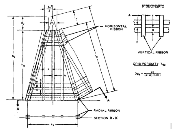
Figure 6-22 shows radial ribbons on the same side of the gore rather than on alternate sides. This arrangement eliminates the canopy's tendency to rotate because of the venetian-blind-type connection of gores. Double vertical ribbons on both sides of the horizontal ribbons are connected with three rows of stitching and are necessary for parachutes that operate for longer periods of time at high Mach speeds and high dynamic pressures. Single vertical ribbons are sufficient for low-speed operation, as for aircraft drag parachutes. Figure 6-22 shows fullness in the gore at the vent of the canopy, ev* , instead of at the gore width, ev. The fullness in the upper part of the gore provides stress relief, as previously explained in connection with Figure 6-16.
Some older sources, such as Reference 5.39, recommend a vent area of 1% of the total canopy area, with a resultant 10% vent diameter. This vent area is too large. especially for reefed parachutes (Reference 6.13). A vent area that is 0.25% of the canopy area is a more practical approach.
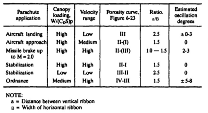
All ribbon parachutes should be equipped with pocket bands to enhance reliability and uniformity of canopy inflation. Section 6.3 describes the design and operation of pocket bands. Figure 6-23 and Table 6-3 give the recommended total canopy porosity, λT, as a function of canopy diameter and application. The figure shows that a 3-foot-diameter ribbon parachute needs a total porosity of 33 to 35% for proper aerodynamic performance, whereas a 100-foot-diameter parachute must reduce the total porosity to about 12%. This reduction results in fast, uniform inflation; good stability; and the quoted aerodynamic coefficients.
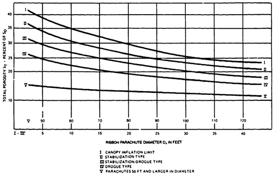
The aerodynamic characteristics of ribbon parachutes are determined primarily by the total canopy porosity, λT and the effective porosity, λe , or, more precisely, by the allowable change in effective porosity, λe . The total porosity is the product of the grid porosity of the gores, λg , and the material porosity of the textile members of the canopy, λm . The effective porosity defines in qualitative terms the increase in geometric porosity, λg , caused by the turning of the horizontal ribbons under high-pressure operation.
Figure 6-24 explains the effect of vertical ribbon spacing, a, and canopy loading, W/(CDS)p, on the effective porosity change and the associated opening behavior of the canopy. The design porosity, λT , increases under internal canopy pressure because of the turning of the horizontal ribbons, called the venetian-blind effect. The increase in the porosity caused by the ribbon turning becomes greater as the ratio of vertical ribbon spacing, a, to horizontal ribbon width, B, and the dynamic pressure increase. The change in slot opening as a function of vertical ribbon distance is shown in lines I and Il and the resultant change in effective porosity in line III of Figure 6-24. Lines IV and V of Figure 6-24 show how parachutes of different canopy loading react to the change in effective porosity. This increase in effective porosity, if not properly controlled in the design of the canopy, can reach the point of critical porosity, causing the canopy to open only partially or not at all.
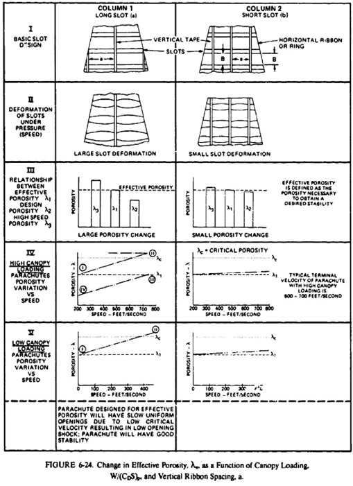
Low-canopy-loading parachutes, such as large final descent parachutes, generally have sufficient drag, even with a partially inflated canopy, to reach lower velocities where the canopy will inflate fully. This may not be the case with high-canopy-loading parachutes, such as first-stage drogue chutes and ordnance retardation parachutes.
As a rule, high-canopy-loading parachutes require a short vertical ribbon spacing, whereas low-canopy-loading parachutes benefit from wider vertical ribbon spacing to obtain a slower, lower-force canopy inflation. The relationship of ribbon parachute application, canopy porosity, and vertical ribbon spacing is shown in Table 6-3.
Section 7.4 covers the design of a supersonic conical ribbon parachute, including several methods for determining the canopy porosity.
Reference 6.14 describes the design of a ribbon parachute with continuous horizontal ribbons and nonparallel vertical ribbons.
Computers are well suited to determine the geometric gore design of ribbon parachutes.
Ribbon parachutes that do not perform as expected may have been designed without following the generally known design principles that are presented in this manual.
Hemisflo Ribbon Parachute. Hemisflo ribbon parachutes have been used at velocities up to Mach 3, primarily as drogue and stabilization devices and for applications where the parachute must operate for longer periods of time in the supersonic region and often in the wake of a large forebody.
Typical applications are as stabilization and retardation parachutes for several types of ejection seats, for the encapsulated seats of the B-58 and B-70 bombers, and as first-stage drogue chutes for the F-111 and the B-1 crew modules.
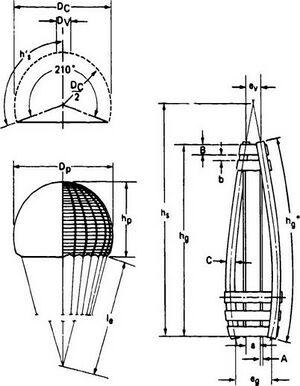
The canopy of the hemisflo parachute forms part of a perfect sphere with the suspension lines connected tangentially to the sphere (see Figure 6.25),
where:
The point where the lines contact the canopy becomes the canopy skirt, resulting in a 210-degree canopy (see Figure 6-25). The hemispherical shape avoids the use of gores that can flutter in and out, as on flat or conical canopies, and eliminates the length difference in the leading and trailing edges of the horizontal ribbons. This greatly reduces canopy breathing and high-frequency ribbon flutter, both sources of canopy damage and drag decrease on conical ribbon parachutes operating at supersonic velocities. All detail design recommendations of conical ribbon parachutes also apply to hemisfio canopies. Figure 6-25 shows horizontal ribbons on alternate gore sides. As previously explained. this arrangement may cause a venetian-blind effect and can lead to canopy rotation. Having both radials on the same side will decrease rotational tendencies.
Reefing of hemisflo canopies is similar to that of other ribbon parachutes. The reefing ratio and reefing-line force data for conical ribbon parachutes have been used with good results on hemisflo canopies. References 5.51, 5.52, and 6.15 through 6.18 give performance and design details for hemisflo ribbon parachutes.
Hyperflo Parachute. The hyperflo parachute was developed simultaneously with the hemisflo parachute by the Cook Research Laboratories in the supersonic decelerator program. The hyperflo parachute canopy has a flat ribbon grid crown and an inverted cone of solid material at the skirt, somewhat similar to the extended-skirt parachute. It has been tested in wind-tunnel, sled, and free-flight tests up to Mach 4. The hyperflo parachute is sensitive to variations in design. velocity, and dynamic pressure, and requires extensive testing before operational use; this need for testing has limited its application. Reference 6.17 and 6.19 describe hyperflo development, testing. and performance.
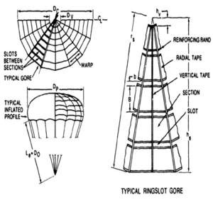
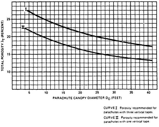
Ringslot Parachute. The ringslot parachute, developed as a low-cost supplement to the ribbon parachute, has similar aerodynamic characteristics, but has a 10 to 14% higher drag. The basic design shown in Figure 6-26 has been used with both a flat and a 25-degree conical canopy. The horizontal ribbons of the ribbon parachute are replaced with rings manufactured from full-, half-, or quarter-width standard parachute material. Individual segments are joined to rings that are reinforced on the upper and the lower edges; the rings are then joined using radial tapes. Specification MIL-C-9401 gives many design details. Rings have been manufactured from continuous pieces of material with V-type folds under the radial tapes. Landing deceleration and platform-load-extraction parachutes are multiple-use parachutes that need reinforcing between the rings and vertical tapes. As on ribbon parachutes, the number of vertical tapes in each gore depends on the canopy loading. landing deceleration and platform-extraction parachutes that have a high canopy loading need three vertical tapes: low-canopy-loading ringslot parachutes, developed for the high-speed drop of supply containers, need only one vertical tape for a slower, lower-force opening. As with ribbon parachutes, the ringslot parachute's aerodynamic performance is controlled by the total porosity and the allowable increase in effective porosity. Figure 6-27 shows the total porosity as a function of parachute diameter, and number of vertical tapes.
Ringslot parachutes for platform extraction are being used in clusters of two and three parachutes (References 5.48 and 5.49).
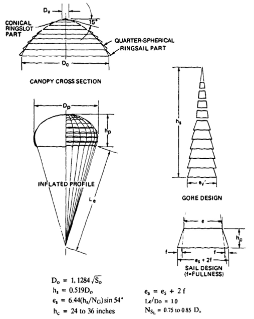
Ringsail parachute. The ringsail parachute, a modification of the ringslot parachute, has a quarter-spherical cross section in the lower part, and a conical cross section in the upper part of the canopy. The cut of the rings in the crown area is similar to that of the ringslot parachute. In the lower part of the canopy, each ring section has fullness in the leading edge of the ring that gives each section a positive angle of attack. This creates an outward-directed force that, in turn, provides a larger drag coefficient and a faster canopy inflation. The faster inflation increases the opening-force coefficient, CX, to 1.2, compared to 1.05 to 1.1 for the ringslot parachute.
The ringsail parachute, whose basic design is shown in Figure 6-28 and described in detail in Reference 5.50, was used as main descent parachute for the three manned spacecraft, Mercury, Gemini, and Apollo (References 5.10, 6.90, and 6.91), and for the crew modules of the F-111 and B-1 bombers (References 5.169 and 5.170). After the Apollo program, NASA funded programs for the development and testing of a cluster of approximately 125-foot-diameter ringsail parachutes and a single 189-foot-diameter parachute; both were successful programs (References 6.20 and 6.21).
The ringsail parachute has a characteristic that is beneficial for a single parachute but creates problems in cluster operation. Large, reefed ringsail parachutes open quickly into the first reefed stage; thereafter, additional rings inflate slowly before disreef. Quick opening is advantageous for single parachutes but creates a lead/lag chute situation in a cluster of three independently deployed Apollo main parachutes. The leading parachute or parachutes further increase in diameter during reefed inflation, crowding out the lagging chute or chutes and causing large differences in opening times and forces. To prevent this situation, a wide slot is placed between the fourth and fifth rings, preventing the leading chute or chutes from inflating further in the first reefed stage and permitting more uniform inflation of all three parachutes.
Disk-Gap-Band Parachutes. The disk-gap-band parachute, a NASA development, was used in the Viking program for assisting in the landing of two probes on Mars. The disk-gap-band parachute consists of a flat solid material top, a cylindrical extension on the canopy skirt, and a single slot or gap between the top and the extension, somewhat similar to a one-slot ring-slot parachute. References 5.55 and 5.56 and 6.22 describe design and testing of this parachute.
6.3 DESIGN OF PARACHUTE ASSEMBLIES AND COMPONENTS
A parachute assembly consists of several components (a typical assembly is shown in Figure 6-11). In addition, the total parachute system may consist of a cluster of several parachute assemblies. This section describes the design and operation of the various components that constitute a parachute assembly.
6.3.1 Parachute Clusters
6.3.1.1 Cluster Configurations
Three typical parachute cluster configurations are shown in Figure 6-29. Configuration (a) is used on parachute clusters for the airdrop of heavy military equipment and has been used successfully for loads up to 50,000 pounds and clusters of 10 100-foot-diameter G-11 cargo parachutes. Platforms containing the loads are extracted from the cargo compartment of the aircraft by a single parachute or a cluster of two or three ringslot parachutes. After the platform has left the aircraft, the extraction-parachute assembly is disconnected from the platform and lifts the tied-together main parachute deployment bags off the platform. The extraction parachute then serves as pilot chute for the deployment of the main parachutes. The extraction chute/pilot chute/bridie/deployment-bag assembly disconnects from the main parachutes and must be retrieved individually.
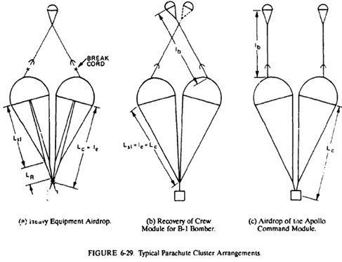
Cluster configuration (b) was used on the three ringsail main parachutes for landing the B-1 bomber crew escape module, a now discontinued concept. The cluster was begun using the independently deployed main parachute concept of the Apollo spacecraft but was changed to configuration (b), which stretches all parachutes simultaneously, resulting in more uniform deployment, canopy inflation, and opening forces. Each pilot chute was able to deploy the total cluster. The second pilot chute served as backup. References 5.169 and 5.170 describe the B-1 crew module parachute system.
Configuration (c) was used on the three 85.3-foot-daimeter Apollo ringsail parachutes. Parachutes on manned spacecraft are the primary means for landing the astronauts. NASA, therefore, ruled that no failure of a subsystem or component should cause a catastrophic system failure. This ruled out common pilot chute and common riser connection points as on configurations (a) and (b). The two drogue chutes and the three main parachutes had to be individually deployed, connected, and disconnected, a major design complication.
Configuration (a) has three single failure points: a single pilot chute, a common pilot chute junction point, and a common riser connection fitting.
Configuration (b) has two single failure points: the fittings that connect the two pilot chutes to the bridles that lead to the main parachutes and the confluence point of the two main parachute risers. These single failure points were acceptable for the B-l aircraft since the parachute-recovered crew module does not constitute the primary landing system, as do the parachutes on the Apollo spacecraft, but constitutes an emergency backup system. The pilot chute bridles on configuration (b) must be long enough to allow full inflation of all canopies plus a distance of about 0.1 Dp between adjacent parachutes.
Configuration (c) has no single failure points because of the independent deployment of each parachute assembly consisting of a permanently connected pilot chute, a pilot chute bridle. a main parachute deployment bag, a main parachute, and a riser. The independent deployment of the three main parachute assemblies of the Apollo spacecraft caused nonuniform parachute stretch and canopy inflation, resulting in opening-force variations. This problem is discussed in section 5.10.
A parachute cluster with two independently deployed main parachutes is described in Reference 5.23, shown in Figure 7.7, and detailed in section 7.3.
6.3.1.2 Effective Suspension-Line Riser Length
Section 5.10 discusses the loss of parachute drag in a cluster caused by interference between the parachutes and recommends using longer suspension lines or risers to recover some of the interference drag loss. Data on the drag gain caused by longer suspension lines can be found in section 5.2.
Both longer suspension lines and longer risers were used successfully on the Apollo main parachute cluster, with a negligible drag loss in the parachute assembly.
6.3.1.3 Permanently Attached Pilot Chutes
Large, reefed parachutes often exhibit irregular canopy crown inflation; the inflated part of the canopy waves and the vent opening is not properly centered, which causes friction burn and damage in the canopy crown area. Permanently attached pilot chutes stabilize the canopy crown area, prevent friction burns, and support uniform canopy inflation. The distance between the vent of the main parachute and the leading edge of the pilot chute, Lb, should be long enough to permit inflation of the pilot chute in airflow behind the vehicle (see Figure 6-29). Proper distance is especially important for deployment behind large, blunt forebodies. The forebody wake effect is discussed in detail in section 5.2. The pilot chute bridle also must be long enough to permit full inflation of all parachutes in the cluster, allowing a space equal to about 10% of the inflated canopy diameter between the individual canopies. The pilot chute should stay inflated during the reefed canopy opening but should collapse after full canopy inflation.
Several operational clusters with permanently attached pilot chutes used a pilot chute bridle line length of Lb equal to 0.4 to 0.55% of the diameter of the main parachute.
6.3.1.4 Canopy Ties
The individual parachutes in the cluster wander around slowly and change position in a random fashion, but seldom touch. This behavior has never caused any aerodynamic or stress problems but looks awkward. Sandia National Laboratories has successfully used short tie lines to connect the canopies of ribbon and ringslot parachutes, but this technique has been tried unsuccessfully on clusters of less stable parachutes. Unstable canopies in a cluster appear to fight this restriction and cause large canopy deformations.
6.3.1.5 Canopy Vent Size
Most large parachutes use reefing for force control and for uniform inflation in the reefed stage. Experience has shown that the diameter of the vent of the reefed canopy must be substantially smaller than the diameter of the reefing-line circle to ensure good canopy inflation. The sometimes-used rule of thumb to make the vent area of the canopy equal to 1% of the total canopy area results in a vent too large for most reefed large parachutes. Problems with a large vent on the large ribbon parachutes for the recovery of the Space Shuttle solid booster rockets are discussed in Reference 6.13.
6.3.1.6 Cluster Parachute Deployment Bags
Cluster parachutes have been stowed successfully in individual bags as well as in a single compartmented bag. The choice of the deployment-bag configuration depends mostly on the shape of the payload and the type and shape of the compartment available for parachute storage.
Stowage of the parachutes in odd vehicle locations, parachute packing, rigging, and ground retrieval influence the selection of single or multiple deployment bags. Forced ejection of the parachutes in cross-wind deployment may favor the selection of a single, compartmented deployment bag.
6.3.1.7 Cluster Parachute Literature
Extensive literature is available on parachute cluster design and operation. References 5.1, 5.10, 5.23, and 5.164 to 5.179 provide information on many aspects of cluster design.
6.3.2 Pocket Bands
Pocket bands are an essential design element of all slotted parachutes and are beneficial to most solid material, standard-porosity canopies. Pocket bands support the inflation of high-porosity slotted canopies and make inflation times and forces of all parachutes more uniform by eliminating random long and short inflation times.
The author developed pocket bands during World War Il to counteract the uncontrolled infolding of canopy gores of high-porosity ribbon parachutes. This gore infolding was especially pronounced in the wake of large forebodies. The design detailed in Figure 6-30 and Table 6-4 evolved from investigations of various pocket band configurations (References 5.39. and 6.23 to 6.25).
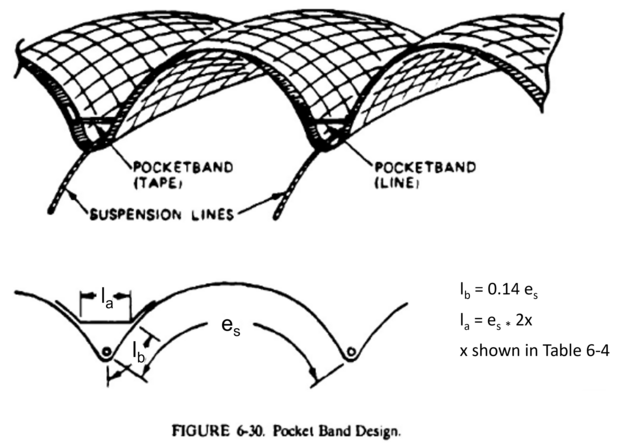

Sandia National Laboratories recently investigated, in wind-tunnel tests, the effect of pocket bands on the inflation of fully open and reefed ringslot parachutes. Sandia's conclusion reads, "The effect of pocket bands on any parachute is to produce repeatable minimized inflation times" (Reference 6.25). Pocket bands must be dimensioned so as not to restrict full canopy inflation. Different canopy types and different numbers of gores require different pocket band dimensions, as shown in Table 6-4. Extended-skirt parachutes, for example, have a flatter gore shape at the skirt than flat and conical canopies have and therefore need longer pocket bands. Use of round lines or small tapes as bands does not change the canopy inflation time. but 2-inch-wide pocket bands decrease the canopy inflation time by 15 to 25%.
Pocket bands should have a strength equivalent to 50% of that of the suspension lines or skirt tapes. Most parachute companies use pattern sewing machines for attaching the pocket band to the skirt of the parachute canopy.
The use of pocket bands for obtaining a small amount of canopy reefing, called "fixed reefing," is described in section 6.5.
6.3.3 Pilot Chutes
Pilot chutes are used to deploy large parachutes from their storage packs or containers into good airflow behind the jumper, load, or vehicle. A typical pilot chute and main parachute assembly is shown in Figure 6-4; the main parachute is stowed in a deployment bag. A pilot chute, attached to the bag, first extracts the parachute pack from the vehicle compartment and then deploys the main parachute from its deployment bag. The following requirements, based on experience, can be defined for pilot chutes:
l. Pilot chutes must open quickly and reliably.
2. Pilot chutes must be stable and must have sufficient drag to pull the main parachute pack away from the payload and extract the main parachute.
3. A pilot chute, ejected by its internal spring. drogue gun, or mortar into good airflow behind the forebody, must be able to extract and deploy the attached parachute or the parachute deployment bag.
Many types of pilot chutes have been used successfully and meet the requirements stated above. The most frequently used pilot chute for the deployment of military personnel emergency parachutes is the MA-1 type shown in Figure 6-31. This chute has a 30-inch-diameter canopy of low-porosity material. An internal coil spring ejects the pilot chute away from the jumper. Vanes attached between the suspension lines and the material cone that covers the internal spring orient the pilot chute in the direction of the airflow (Reference 6.26). A modified version with a simpler canopy design and a heavier spring than that of the MA-1 is used with sport parachutes.
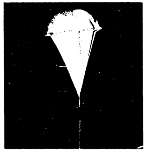
A box-type pilot chute without an internal spring but with stabilizing vanes has been used for numerous applications where the pilot chute is extracted by a drogue gun slug or is mortar-ejected (Figure 6-32). Ribless guide surface and ringslot pilot chutes have been used successfully for many projects.
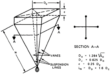
Mortar-ejected 7.5-foot-diameter ringslot parachutes were used as pilot chutes for disconnecting the Apollo main parachute deployment bags from the command module by means of a daisy chain, and for deploying the main parachutes. Pilot chutes must be ejected into good airflow behind the forebody. Tests conducted by several sources resulted in the recommendation to eject the pilot chute to a distance equivalent to at least four and, if possible, six times the forebody diameter behind the vehicle.
Evaluation of pilot chute failures at the El Centro parachute test range led to the rule of thumb that the pilot chute extraction force should be equal to or larger than four times the weight of the parachute assembly to be extracted.
Tests conducted with ribbon parachutes deployed behind a test-bed aircraft showed that a permanently attached pilot chute with a drag area equal to 6% of the main parachute drag area starts to squid the main parachute.
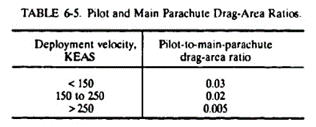
An evaluation of successful pilot chute applications established the pilot and main parachute drag-area ratio as a function of the deployment velocity listed in Table 6-5.
Drag coefficients and opening-force coefficients for pilot chutes are shown in Table 6-6. The drag of a pilot chute close to a forebody may be less than that obtained from the Table 6-6 coefficients because of forebody wake. Figure 5-22 can be used to determine the drag loss.
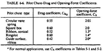
Table 6-5 recommends different sizes of pilot chutes for various deployment velocities. However, the size differences create problems for pilot chutes that must work over a wide velocity range. A single large pilot chute may satisfy the low-speed requirements but may create unacceptable snatch forces and pilot chute weights during high-speed deployment. A small pilot chute would work well at high speeds but would create a deployment problem at low speed. Some projects encountering this velocity-range deployment problem have used a two-step pilot chute or a pilot chute cluster.
Several multiple-step pilot chutes have been developed with low drag area at high-speed deployment and high drag area at low-speed deployment. One concept uses blow-out patches around the skirt of the pilot chute. These patches remain intact at low speeds but blow out at high speeds. Another concept uses a pilot chute with a strong inner canopy part and a weaker outer part. A second set of strong suspension lines is attached to the stronger canopy part at the inside of the canopy. At low-speed deployment, the entire canopy inflates; at high-speed deployment, the outer set of suspension lines breaks away and only the inner small part of the canopy inflates. A cluster of two pilot chutes, a larger light chute and a smaller strong pilot chute, performs the same two-speed function.
6.3.4 Anti-Inversion Net
The T-10 parachute, a 35-foot-diameter extended-skirt design, has been used by several western nations as a paratrooper parachute. After the paratrooper exits the aircraft, the parachute is deployed by a static line attached to the aircraft, similar to the deployment procedure described in section 6.1 and shown in Figure 6-3. The cross-wind deployment of the parachute has a tendency to form a sail, causing canopy inversions when the upwind gore is pushed through two adjacent, downwind suspension lines. The gore forms a pocket on the opposite canopy side or pulls the entire canopy through the downwind side and turns the canopy inside out. Canopy inversion frequently causes extensive canopy damage.
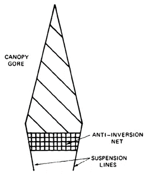
The invention of the anti-inversion net by G.W. Stephens of Great Britain virtually eliminated T-10 inversions. Figure 6-33 shows a T-10 gore with the anti-inversion net installed. The U.S. version of the net uses nylon mesh with a 3.5-inch grid spacing. The net extends 18 inches down from the canopy skirt, forming an inverted cone extension. The British design uses a slightly smaller grid spacing.
Extensive tests conducted in Great Britain and by U.S. airborne troops have demonstrated the effectiveness of the anti-inversion net (References 6.27 through 6.29).
6.3.5 Parachute Deployment Components
Section 6.1 describes various parachute deployment concepts and emphasizes that parachute deployment should proceed in the order of riser, suspension lines, and canopy, and that the mouth of the canopy should be closed until the suspension lines and the canopy are stretched to avoid high mass forces (snatch force). This deployment sequence. called line-first deployment, requires support equipment. Most frequently, a deployment bag is used to house the parachute and riser. Deployment bags need compartments with round, rectangular, or related cross sections and a length-to-width ratio not to exceed about 4 to 1. For odd compartment shapes and locations, other means to support an orderly, sequential deployment have been developed; the most commonly used are skirt hesitators, quarter deployment bags, deployment sleeves, and sacrifice panels. However, this is a field where ingenuity frequently creates outstanding new approaches that ensure good deployment from odd parachute compartment shapes and locations.
6.3.5.1 Parachute Deployment Bags
The most frequently and successfully used method for providing a controlled deployment is stowing the parachute in a flexible textile container, called a deployment bag, that becomes part of the parachute assembly (see Figures 6-4 and 6-11). The deployment bag must be shaped to the configuration of the parachute container or vehicle compartment and designed to control parachute deployment and permit easy handling, packing. rigging, and storage of the parachute assembly.
Pilot chutes or drogue chutes are used to extract the deployment bag and to deploy the parachutes. The deployment bag must provide a tight enclosure for the parachute assembly but must be so designed that parachute and risers can deploy without friction damage caused by a bag that is tight, or by protrusions in the bag. Reference 6.30 describes early ideas about the design and operation of deployment bags.
Many types of deployment bags have been used, ranging from a simple sack with a flap closure for small parachutes deployed at low velocity to a multiple-compartment, multiple-constraint bag for large, final descent parachutes such as those used for the Apollo and F-111 aircraft crew modules.
A typical deployment bag is shown in Figure 6-34. Detail (a) shows the deployment bag cross section consisting of two compartments, one for the parachute canopy (A) and a second for suspension lines and risers (B). The canopy and suspension lines are retained in their compartments with individual ties.
Detail (b) shows two bag closure methods. Method (b) (1) closes the flaps with line or riser stows. A line or riser bundle is routed through two loops that extend from the lower flap through openings in the upper flap. Care must be taken to prevent friction burns when extracting the line bundle. Wrapping the folded line bundle with wrapping paper or lining the stow with cotton or Teflon material are proven methods.
Method (b) (2) shows a circular bag closed with four flaps tied together with a heavy cord; the cord is severed with a shear knife upon deployment. The shear knife must be attached to the appropriate riser or line member that stretches before full riser or line stretch.
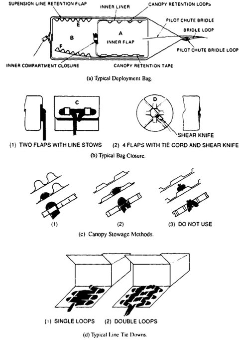
Typical ties for retention of the canopy and for stowage of suspension lines and risers are shown in Detail (c). Canopy ties must be designed to retain each or every second canopy accordion fold and to prevent slippage of the canopy under the ties; slippage will cause friction burns. Both light cords and rubber bands have been used for canopy ties and for tying lightweight suspension lines. Heavier lines and risers are best stowed in individual webbing loops sewn either to the wall of the bag or to fold-out flaps as shown in Detail (c), (1) and (2).
Stowing the suspension lines in two groups as shown in Detail (d) (2) prevents the bag from zigzagging during line deployment.
K. French has presented a theory for calculating the effect of line ties (Reference 6.31). Reference 6.32 presents an interesting approach to testing a deployment system.
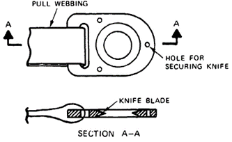
A typical shear knife is shown in Figure 6-35. The knife must be installed so that no tension is exerted on the pull webbing before parachute deployment. The small hole in the shear knife secures the knife in a no-tension position before parachute deployment. The U.S. Army uses shear knives designed to cut multiple-layer webbings. Small shear knives have been made from half-inch-diameter rings.
6.3.5.2 Banana-Peel Bag
The banana-peel bag, also called the longitudinal laced bag, was developed by the Sandia National Laboratories to meet a specific installation (Reference 6.33). This bag is suitable for heavy hand and mechanical pressure packing. The bag consists of a bottom part and several long flaps that form the actual bag (Figure 6-36). The flaps are tied together with strong tie cords through grommets in the flaps. The parachute canopy and suspension lines are retained in the bag, with tie cords and loops on the inside of the flaps. At deployment, shear knives cut the flap tie cords and the bag unravels from the top.
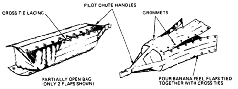
Many variations of the bag shown are possible. However, all bag designs try to control the deployment of the parachute assembly in the sequence of riser, suspension lines, and canopy. All designs also try to keep the mouth of the canopy closed until suspension lines and canopy are fully stretched. A drawback to this bag design is the possibility that the sides can flap after unlacing, potentially causing damage to lightweight canopy material during deployment.
6.3.5.3 Deployment Sleeve
The deployment sleeve is a long cylindrical container that fits loosely over the parachute canopy (see Figure 6-37). Frequently the sleeve ends in a flap that folds over the lower part of the sleeve and is closed with suspension-line stow loops as shown in Figure 6-34, Detail (b). The suspension lines are stowed on the outside of the sleeve in a similar arrangement to that of Detail (d) in Figure 6-34. The deployment sleeve is extensively used by sport parachutists and for parachutes that must be stowed in odd containers; for example, an aircraft spin recovery parachute that is stowed in a flat deployment container near the vertical stabilizer of a fighter aircraft. A closed sleeve is not suitable for deployment in excess of 200 knots because of the danger of friction burns.
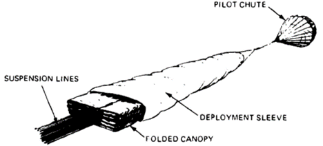
6.3.5.4 Sacrifice Panel
The design of the sacrifice panel or wrap-around sleeve is shown in Figure 6-38. The sacrifice panel consists of an open sleeve attached to one of the canopy radials. The panel is wrapped around the folded canopy and tied together with light thread or a daisy-chain arrangement. Upon deployment, the panel closure is broken or opened, allowing the canopy to inflate. This design avoids friction burn between canopy and sleeve at high speed and retains the sleeve with the canopy.
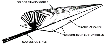
6.3.5.5 Skirt Hesitator and Quarter Deployment Bag
When a full deployment bag is not used, the skirt hesitator serves as a means for keeping the mouth of the canopy closed until suspension-line and canopy stretch occurs, thus preventing premature canopy inflation and a high mass shock. The skirt hesitator shown in Figure 6-39 incorporates two loops that fold around the canopy skirt and are tied together with a break cord that also encloses the bundled suspension lines. Stretching the canopy with a pilot chute severs the break cord and allows the canopy to inflate. This concept prevents high snatch forces and makes canopy inflation more uniform.
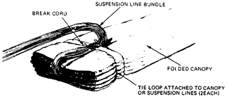
A well-known modification of the skirt hesitator is the quarter deployment bag used on several types of personnel parachutes. The quarter bag is a short bag that encloses the skirt of the parachute canopy and stows the suspension lines in stow loops located under 45 degrees on the outside of the quarter bag, as shown in Figure 6-40. This design keeps the mouth of the canopy closed until canopy and line stretch occurs and ensures an orderly, low-snatch-force deployment.
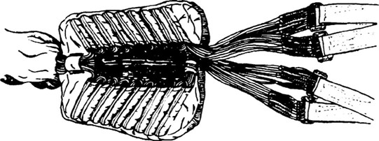
6.3.5.6 General Comments on Deployment
Friction burns from bags or sleeves during parachute deployment are a constant concern in the design of deployment methods. Bags, therefore, are frequently lined with low-friction material such as cotton or Teflon, or made of Spectra. A bag liner may be a fixed liner or a pull-out, turnaround sleeve. All protruding corners, such as the upper ends of the foldout flaps, must be protected and smoothed to prevent canopy damage.
The design of the deployment bag must ensure that the extraction force of the pilot chute is properly guided around the bag and into the closure loops to prevent the bag from being ruptured by the extraction force.
6.4 PARACHUTE STRESS ANALYSIS
6.4.1 Stress Analysis of Parachute Textile Components
Methods established for aeronautical equipment are used to analyze the loads and stresses in the various components of a parachute assembly. However, because textiles are the primary materials used in parachutes, their special material and environmental characteristics must be known and considered in establishing design factors and in dimensioning the various elements of the parachute assembly. Textiles used include cloth and ribbons for the parachute canopy; webbings, lines, and tapes for suspension lines and canopy reinforcements; and various materials for deployment bags and related components. The strength of the woven material differs from the strength of the basic fiber because of the routing of the individual fibers in the manufacturing process of the material, and because of chemical treatment during weaving and finishing.
Textiles, as a rule, are connected by sewing and stitching, which introduces connection losses based on the type of connection used. Natural fibers, and, to a somewhat lesser degree, man-made fibers are affected much more than are metals by such environmental factors as temperature, humidity, radiation (light), chemicals, aging; and such mechanical factors as abrasion, handling, and packing.
It is very difficult to determine the load and stress distribution for a variable-geometry, variable-velocity inflating canopy. Many efforts in the 1950s and early 1960s did not provide a practical solution for stressing parachute canopies. During the Apollo program, Mullins and Reynolds developed a computerized system for calculating the stresses in horizontally slotted canopies in general, and for ribbon parachutes in particular (Reference 6.34). This method, called the CANO method, has been modified and improved by the University of Minnesota and the Sandia National Laboratories. A summary of efforts in this area and an analysis of the CANO program is presented with an extensive bibliography in Reference 6.35 and in abbreviated form in Reference 6.36. The Sandia National Laboratories has recently published a modified and improved version of the CANO program called Canopy Load Analysis (CALA), a computer approach that gives good results for all slotted canopies and acceptable results for solid cloth canopies (Reference 6-37).
Prior to the CANO program, two methods were developed that give good approximations for determining the strength of cloth for solid material canopies and for the required strength of horizontal ribbons in ribbon parachutes. These two methods are described in sections 6.4.3 and 6.4.4. Both methods derive from the established procedure for calculating the hub stress in pressure vessels. These methods may still serve for a preliminary quick check.
6.4.2 Load and Design Factors
The determination of load and design factors follows established procedures in the aerospace industry. The recommended factors are shown in Table 6-7, but they may be changed by agreement between the prime contractor and subcontractor for specific operational or environmental requirements.
In agreement with common practice, a general safety factor of 1.5 is recommended for all non-manrated parachute recovery systems. Primary manrated systems, those where the parachute assembly is part of the operational system and not a backup system, should use a slightly higher safety factor of 1.6. These systems include manned spacecraft parachute landing systems and parachutes for paratroopers, smoke jumpers, and sport parachutists. The same safety factor is recommended for ordnance devices where a failure of the parachute assembly could result in loss of the aircraft and the aircraft crew.
Parachutes for aircraft emergency escape are backup systems to the primary mode of landing the aircraft on its wheels. A safety factor of 1.5 should be satisfactory.
Dynamic Load Factor. The dynamic load factor was established at the request of the Stress Analysis Branch of the Aeronautical Systems Division at Wrigh Patterson AFB and used by NASA on the Apollo program. The dynamic load factor is used only for hard-to-determine loads, such as those encountered in the long bridle lines of the pilot chutes used to extract the Apollo main parachutes (Reference 6.38).
Line Convergence Factor. The forces in the parachute canopy are assumed to act parallel to the line of flight or to the canopy main axis. The suspension lines run at an angle to this axis, thereby experiencing a slightly higher load. For a suspension-line-to-nominal-parachute-diameter ratio, Lc/Do, of 1.0, this factor is 1.05, but changes slightly with longer or shorter lines or inflated-canopy diameter.
Unsymmetrical Suspension-Line Load Distribution. A general assumption used to be that on circular parachutes, the parachute force was evenly distributed among the suspension lines. Recent data has shown that this is not true, and for parachutes in a cluster, the asymmetry may be quite large (see chapter xx). Although this assumption may not be correct, past experience has shown it to be acceptable for both reefed and full open canopies. If force measurements on suspension lines or uneven canopy deployment suggest an uneven load distribution, an appropriate factor should be used.
Ultimate Load Factor. Ihe ultimate load factor is the sum product of the individual load factors. Mechanical, environmental, and material conditions can cause strength losses that are not contained in the loss factors.
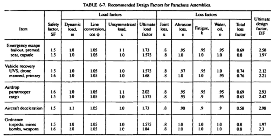
Joint Loss. Whenever textiles are connected to each other or to metals, a loss in joint strength relative to the basic material strength occurs relative to the basic material strength. This loss is best determined by strength tests of the particular connections or established in relation to previously conducted tests. If no tests can be conducted, a loss factor of 0.8 should be used for all connections of nylon tapes, lines, and suspension lines to other elements of the parachute. A similar loss factor appears to be acceptable for the connection of Kevlar lines, tapes, and webbings, but not for Kevlar fabric. fie efficiency of Kevlar fabric seams is lower than that of equivalent nylon seams. Section 6.6.5 discusses designing with Kevlar.
Abrasion Loss. One-time-use parachutes suffer little or no abrasion. However, aircraft landing deceleration parachutes that are used up to 50 times and are occasionally dragged on the ground suffer mechanical abrasion to various degrees.
Fatigue. Fatigue includes strength loss caused by multiple use, high-pressure packing, or a combination of both. Tests conducted during the Apollo program where nylon lines were loaded in short time intervals to 75% of their ultimate strength resulted in a strength reduction combined with a hysteresis-type loss in elongation.
Water, Oil, Sunlight, Vacuum, and Other Environmental Effects. Parachutes that are subjected to multiple use or exposed to sunlight, water, vacuum, and other environmental conditions will suffer a loss in strength. The loss differs for natural and man-made fibers and must be determined based on the operational environment and the materials used. Duplicating the translunar and re-entry environment on the Apollo parachute system did not produce a measurable material degradation from vacuum and radiation exposure. Effects of man-made radiation must be considered where appropriate.
Temperature. All natural and man-made fibers lose strength and melt, burn, or decompose when subjected to high temperatures. Dacron and Nomex are slightly superior and Kevlar is far superior to nylon in temperature resistance. Nylon parachutes in compartments close to engines or in nose cones that experience aerodynamic heating will lose 5 to 7% strength at the generally accepted 200oF compartment temperature. Section 6.6.1 provides information on the effects of environmental conditions on parachute textiles. The unstable Apollo command module required steel-cable risers because of the possibility of contact between the red-hot heat shield and the drogue or main parachute risers.
Ultimate Design Factor. Combining the load, loss, and safety factors produces the ultimate design factor for the various parachute assembly components. A typical design-factor analysis is given in section 7.3. Most parachute textiles have an additional built-in safety factor. Textile specifications define a minimum strength. Manufacturers, to avoid rejections, generally weave the material 5 to 10% stronger than the specification strength, thus providing an additional margin of safety.
General Comments. Parachutes used in ejection seats and crew modules are permanently packed in well-protected containers and repacked only during major aircraft overhauls infrequently. Personnel emergency parachutes worn by aircraft crews are subjected to a certain amount of wear in the process of multiple repacking; the personnel parachutes are carried around and sometimes abused despite regulations to the contrary and therefore have a different design factor.
Aircraft landing deceleration parachutes are designed for high-speed emergency landings without the use of flaps or brakes. In normal use these parachutes are deployed at a dynamic pressure of about 55% of the design level, a considerably less severe operational environment.
6.4.3 Preliminary Stress Analysis Method tor Solid Material Canopies
The CANO and CALA computer programs, along with more recently-developed parachute modelling programs, are the final methods for determining loads and stresses in parachute canopies. However, two methods for approximate dimensioning of canopy fabric and horizontal ribbon strength, used successfully in the past, can be used for quick preliminary analysis.
In the first method, a comparative analysis can be made from the well-defined stress in a cylindrical vessel. The hub stress, tc, in a cylinder is determined by
tc=pr/2 lb/unit width
where p is the pressure in the vessel in lb/in 2 and r is the radius of the cylinder. The hub stress increases linearly with increased pressure, and decreases linearly with reduced radius.
Each gore of an inflating canopy may be considered part of a pressure vessel with variable radius, where the stress in the canopy increases linearly with the dynamic pressure or the related maximum parachute force, Fx, and decreases linearly with the radius or the related canopy diameter.
Using this approach, E. Ewing proposed the following formula for the stress-per-unit width for the fabric in a solid material canopy:
tc=Fx/Dp12 * DS lb/in.
Where:
tc = required material strength, lb/inch width
Fx = maximum parachute opening force, reefed or unreefed, lb
DS = ultimate design factor (see Table 6-7)
Dp = projected (inflated) canopy diameter, feet
The projected canopy diameter can be determined from Tables 5-1 to 5-4, which give the ratio Dp/Do for the most common parachute types.
The inflated diameter of a reefed parachute, DPr , can be calculated from the known reefed drag area, (CDS)p. Assuming a 0.6 drag coefficient, CDr, for the reefed parachute for slotted canopies and a 0.8 drag coefficient for solid fabric canopies, the equivalent reefed canopy area is:
Sor=(CDS)pr/CDr
and the equivalent reefed nominal diameter is:
Dor=1.1284Sor and Dpr=Do C with C = 0.67
where a CD of 0.65 is recommended. The value for the inflated full open canopy diameter is a good approximation. The projected diameter of the reefed canopy is less accurate. Therefore, a conservative approach should be used in the canopy material selection for the reefed parachute area.
6.4.4 Stressing of Horizontal Ribbons in Ribbon Parachutes
The second method is a somewhat similar analysis developed by the author for stressing the horizontal ribbons in ribbon parachutes. Using the determination of hub stresses in cylindrical pressure vessels as an analog, a pressure definition:
Fx /(CDS)p
is formed with Fx again the maximum parachute force and (CDS)p the parachute drag area. The radius relation is again expressed as gore width at the skirt of the canopy. Based on evaluation of numerous operational parachutes, curves have been plotted for the required ribbon strength (Figure 6-41).
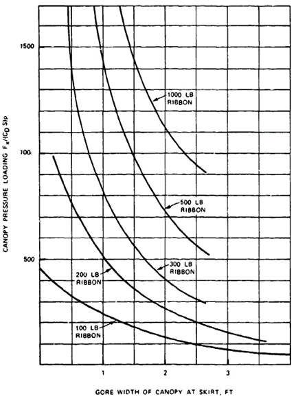
Stress in reefed parachute canopies is calculated in the same manner as that in solid fabric canopies. The approach has provided good preliminary results for many ribbon parachutes. As previously stated, the availability of the CANO and CALA computer programs relegates this method to the quick, preliminary-approach status.
6.4.5 Stress Relief in the Canopy Crown Area
The hub-stress formula shows that the stress in a cylindrical pressure vessel as well as in the gore of an inflating canopy decreases with the gore radius. The inflating canopy gore has a radius in most of its length except at the vent of the canopy. A radius at the vent can be designed into the canopy by providing surplus canopy width in the vent area (see Figure 6-22) where the gore width at the vent, ev, is increased to the dimension ev*. Gathering the vent with the vent tape to the original dimension, ev, now provides a radius at the vent.
The author conducted a weight-optimization analysis between the increase in gore radius, the decrease in required material strength, and the weight increase caused by the wider gore (Reference 5.39). This analysis showed that a 10% increase in gore width was an acceptable solution.
Section 7.3.9 describes the process of calculating the gore dimensions, including the gore widening at the vent. for a 74-foot-diameter extended-skirt parachute.
6-4.6 Dimensioning of Suspension Lines, Risers, and Canopy Vent end Skirt Tapes
Maximum parachute forces and the design factors discussed in section 6.4.2 govern the dimensioning of suspension lines, risers, and radial tapes. Dimensioning of vent and skirt tapes is a combination of experience and calculation. Chapter 7 of this manual includes the design of a solid material parachute cluster assembly and a ribbon parachute assembly. This design includes the dimensioning of all components including discussions of fullness in the canopy fabric as well as in skirt and vent tapes and in the vent bands.
Section 6.6.4 "Designing in Textiles," should be carefully studied before the design and dimensioning of a parachute assembly and all its components is started. The Sandia National Laboratories has developed a practical method for calculating the snatch force of a deploying parachute assembly (Reference 6.39).
6.5 REEFING SYSTEM DESIGN
6.5.1 General
Parachute reefing refers to a method of controlling the stepped inflation of a parachute canopy. The aerodynamics and the system aspects of reefing are discussed in section 5.6.
This section describes the design of the various reefing systems and the components used in the reefing installation and discusses good and poor design approaches based on past experience. The reefing installation is a critical part of a parachute assembly, because a malfunctioning reefing system frequently causes a catastrophic system failure.
The sequence of reefing in this manual is defined by the number of reefing steps. A two-step reefing installation has two reefing steps but three parachute-inflation stages, or, aerodynamically speaking, three different drag-area levels: initial reefed-canopy inflation, an intermediate step, and final full open canopy.
Skirt reefing (see Figure 5-66 in section 5.6) is the most frequently used reefing concept for circular canopies. The introduction of noncircular parachutes, such as the Rogallo parawing and the parafoil (called the square chute by sport parachutists), has introduced slider reefing (shown in Figure 5-70) and modifications of the skirt reefing methods to fit these noncircular parachutes. Several unusual reefing concepts and attempts to develop a continuous disreefing system are described in the literature but have not been used.
6.5.2 Reefing System Installation
Figure 6-42 shows a typical skirt-reefing installation as viewed from under the inflated canopy. A reefing ring is attached to each connection point between the canopy skirt and suspension line, except on two opposite points where reefing cutters are installed. A continuous reefing line runs through all rings and two cutters. The length of the reefing line is determined by the required reduction in canopy drag area (reefing ratio). A typical reefing-line calculation is shown in section 7.3.
Figure 6-42 also shows a reefing ring installed in the middle of the upper left right-hand gore. Additional reefing rings have been used on wide gores of large parachutes to restrict midgore flutter of the uninflated gore during the reefed phase. This arrangement is called midgore reefing.
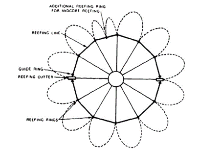
The reefing cutters containing time-controlled, pyrochemically actuated knives sever the reefing line. The cutters are aligned with the reefing line by two guide rings, one installed on each side of the cutter. Figure 6-43 shows a typical reefing cutter installation with the two guide rings on either side of the cutter. Cutter action is begun by pulling a ring at one side of the cutter. A cord, attached on one side to the cutter ring and on the other side to an appropriate part of the parachute assembly, starts the cutter action.
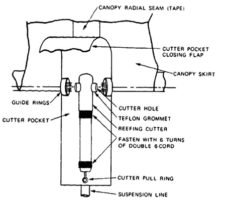
Reefing cutters must be securely fastened to the canopy structure to prevent cutter shift or breakaway. Reefing cutter accelerations of up to 1000 g have been measured during high-speed deployment of parachutes. Two and sometimes three cutters have been used to ensure reliable cutting of the reefing line or lines. The Apollo main parachutes used two reefing lines in the first reefing stage as a safety measure against lines rupturing prematurely, or failure to fire of one reefing cutter. This system results in a complex reefing system installation.
Three different methods of fastening the reefing-line cutters to the canopy are shown in Figure 6 44.
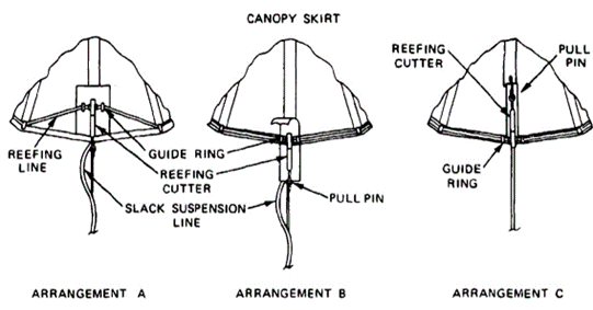
Arrangement (A), used in the early days of reefing, requires little canopy modification, but routes the reefing line in a sharp angle from the reefing rings to the cutter hole. This arrangement can cause high longitudinal loads in the cutters, making the cutters rip out and damage or sever the reefing lines. Installation of strong guide rings on each side of the cutters will absorb the longitudinal forces and improve the installation, but this is not a completely satisfactory solution, especially when heavy cutters and heavy reefing lines are used.
Arrangement (B) is the most frequently used system. This arrangement aligns the reefing line as the line runs through the cutter and avoids radial forces and chafing of sharp edges of the cutters. However, arrangement (B) requires a modification of the canopy and necessitates care in packing the parachute since the cutter extends beyond the canopy.
Arrangement (C) reverses the cutter installation and attaches the pull cord for the cutter pin to the canopy instead of to the suspension lines. The U.S. Army successfully uses arrangement (C) for the G-11 and G-12 cargo parachutes. However, these parachutes are deployed at a relatively low velocity of 130 to 140 knots and experience low canopy-skirt accelerations. Using the same cutter installation on a 38-foot-diameter extended-skirt parachute for the encapsulated seat in the B-70 aircraft resulted in cutter malfunctions.
Deploying the parachutes using arrangement (C) at 250 knots resulted in cutter accelerations that prevented the firing pin in the cutter from properly indenting the percussion cap and initiating the cutter action. Similar results have been reported on other projects.
Many projects in the past have required multiple-step reefing. These have included the landing parachutes for the Apollo command module, the Space Shuttle solid boosters, the F-111 aircraft crew module, several Sandia projects, and especially large hi-glide parachutes for space vehicles and aircraft escape. These later parachutes need three or more reefing steps to handle the high opening forces associated with parachutes manufactured from low-porosity fabric. (References 6.40 to 6.42).
Figure 6-45 shows a typical reefing line and reefing cutter installation for a two-step reefing system. This installation introduces the problem of two lines running through the same reefing rings; entanglement can result when the second-stage reefing line is considerably longer than the first-stage line.
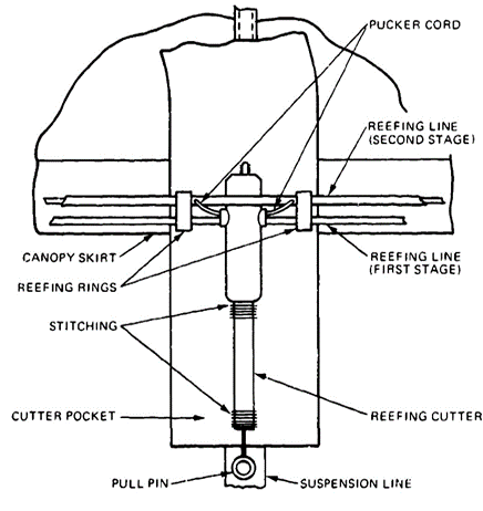
Two designs have been used successfully to overcome reefing line entanglement. Figure 6-45 shows a pucker cord needled through the hollow core of the second-stage reefing line. This pucker cord is the same length as the first-stage line and contracts the second-stage line to the length of the first-stage line. The pucker cord is then guided through the first-stage reefing cutters. Cutting the first-stage line also cuts the pucker cord of the second-stage line and allows the second-stage reefing line to extend fully.
Another method pulls the surplus length of the second-stage reefing line on four diagonally opposed places and stows the surplus line in small pockets from which it extracts when the first-stage reefing line is cut. Care must be exercised with this design to allow the free pull out of the stowed part of the second-stage reefing line. The reefing cutters for the second stage are usually placed under 45 degrees to the first stage cutters.
The heavy reefing lines for the two reefing stages of the drogue and main ribbon parachutes for the recovery of the solid rocket for the NASA Space Shuttle cannot be guided through single reefing rings. The first-stage reefing line, therefore, is located 1 foot above the skirt of the drogue and main parachutes. This necessitates reinforcing this part of the canopy to accommodate the forces of the reefing system, On an overload test of the Space Shuttle solid rocket booster (SRB) drogue chute, the first-stage reefing assembly, including all rings, ripped away from the canopy without breaking the reefing line, causing immediate inflation into the second reefing stage and rupturing the second-stage reefing line, allowing the canopy to inflate fully. This action resulted in explosive destruction of the parachute canopy at a force in excess of 500,000 pounds; the highest parachute force ever measured in the western world. Ihe SRB reefing system is described in References 6.40 and 6.41.
The Apollo main parachutes had a two-stage reefing system that included dual lines for the first-stage reefing, for a total of three reefing lines. This arrangement was necessary because of a NASA requirement to safeguard against not cutting and premature cutting. A probability analysis had shown that premature cutting of the first-stage line but not the second-stage line would result in a catastrophic failure of the parachute system. A dual reefing ring was developed to house the two first-stage reefing lines, Reference 6.43.
Hi-glide parachutes of the Rogallo parawing and the parafoil type have 60 to 70% higher opening forces than circular canopies manufactured from standard-porosity fabric. This requires more reefing stages to accommodate the higher opening forces,
A Rogallo parawing was investigated for an Apollo land landing system. This uncompleted program included aerial drop tests with a 4000-square-foot parawing airdropped at an altitude of 18,000 feet and a dynamic pressure or 90 lb/ft2. Parachute opening forces were limited to the equivalent of 35 g, resulting in four reefing stages. The installation of the reefing system with heavy reefing lines routed around different parts of the uneven skirt of the noncircular canopy, with rings and reefing cutters at various distances from the skirt, was extremely difficult and prone to errors. Color coding was required for all parts belonging to a specific reefing stage, and multiple checking and rechecking was required to prevent reefing lines from running through and around the wrong reefing rings and cutters; this problem is usually not mentioned in final reports. References 6.44 and 6.45 describe this very successful program and its reefing system.
NWC investigated the use of a parafoil (square) parachute for aircrew escape as part of an ejection-seat system. The program, described in Reference 5.161, met the requirement of limiting the parachute opening force to 15 g when used at a 15,000-foot attitude and a speed of 300 KEAS. A three-step reefing system with a modified skirt-reefing concept was necessary to meet the requirements of this successful program.
Reference 6.46 describes how the problem of the reefing-line damage at the cutter was solved by running an independent line through the reefing cutter and tying the reefing line ends into this line loop. Firing the cutter cuts the line loop, which in turn releases the ends of the reefing line.
Reference 6.47 describes another reefing design developed by Sandia National Laboratories. This design uses a three-parachute cluster to replace the F-111 crew module main parachutes. All three parachutes are disreefed simultaneously from a single. centrally located reefing unit.
Variations in the pyro-time train of reefing cutters can cause different times in cluster disreefing, especially at long reefing times. This problem is discussed in more detail in section 6.5.3.
6.5.3 Reefing System Components
6.5.3.1 Reefing Rings
In the early days of reefing system applications, it was necessary to design the reefing rings with a flat profile to prevent the reefing rings from turning and squeezing the reefing line between the rings and the canopy. Figures 6-46 and 6-47 show three different designs for reefing rings. The Type (a) rings in Figure 6-46 are the standard reefing rings in accordance with MIL-STD-MS 27762. The ring labeled Type (b) was developed by Northrop Ventura during the Apollo program to prevent reefing ring deformation during heavy pressure packing, a common occurrence with Type (a) rings. These Type (b) rings are being manufactured from high-strength aluminum alloys.
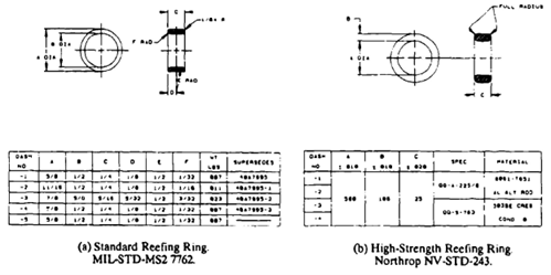
Figure 6-47a shows a dual reefing ring also developed by Northrop during the Apollo program to accommodate the dual first-stage reefing lines of the main parachutes.
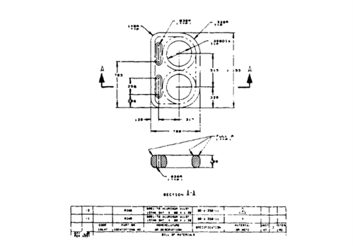
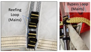
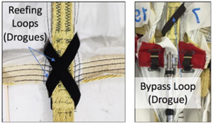
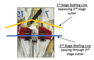
Special heavy-duty reefing lines have been developed by the Sandia National Laboratories.
As a result of reefing ring damage due to high pressure packing, the U.S. Navy began using textile reefing loops in place of reefing rings, Reference 6.92. Reefing loops consist of a narrow Kevlar tape inside a Teflon sleeve sewn to the parachute skirt like a belt loop in the same locations as reefing rings; see Figure 6-47b, which is the reefing loop configuration for the Orion main parachutes, and Figure 6-47c, which is the reefing loop configuration for the Orion drogue parachutes. The reefing line is routed through these reefing loops and reefing cutters in the same manner as with reefing rings, but as the reefing loops are much lighter than reefing rings and are not damaged by pressure packing, this method has become popular for systems requiring high pressure packing. One issue has been discovered when using multiple stages of reefing with reefing loops. When a bypass loop is placed above a cutter to guide a different reefing line around that cutter, the placement of the bypass loop results in an out-of-plane load on the loop which can damage the bypass loop, see Figure 6-47d, Reference 6.93. To prevent this occurrence, reefing loops for each stage should be in the same plane, which could mean positioning the second stage loops and cutters above the first stage loops and cutters.
6.5.3.2 Reefing Line Cutters
The reefing cutters that sever the textile reefing lines contain the following components: a reefing cutter body, a mechanical or electrical actuator, a pyro-initiator, a pyrochemical time train, a booster charge, a shear knife, and an anvil. Reference 6.48 gives a good description of the design and operation of reefing cutters.
The three primary groups of cutters used are shown in Figures 6-48 through 6-50.
The cutter in Figure 6-48 belongs to a series of commercially available cutters that are used for many applications, especially in lightweight main descent parachutes. These mechanically actuated cutters use a firing-pin spring that is unloaded before use and cocked by the extraction of the pull pin from the cutter body. The cutter pull pin line is attached to an appropriate part of the parachute assembly (see Figure 6-44). It is important that the hole in the reefing cutter is properly aligned with the reefing line, and that the cutter hole is smooth and well rounded to prevent damage to the reefing line. The reefing cutter must be properly secured to the canopy skirt to handle the high accelerations encountered during canopy deployment.
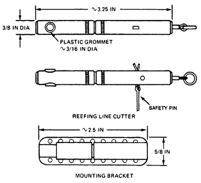
The cutter shown in Figure 6-49, called the M21 cutter, is the standard U.S. Army cutter used in the 100-foot-diameter G-11 and the 64 foot-diameter G-12 cargo parachutes (see specification MIL-C-46992). Figure 6-49 shows that the U.S. Army cutter is installed in what may be called an upside-down position. The acceleration that these cutters experience at the low deployment velocity does not interfere with proper cutter action.
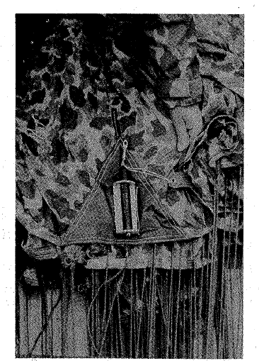
The Figure 6-50 reefing cutter is a heavy-duty cutter developed by the Sandia National Laboratories. This cutter is actuated by an electrical signal from the primary body. The development of this MC 3133 reefing cutter is described in References 6.49 and 6.50. The electrical signal is much more accurate than the pyrochemical time train. In addition, the temperature sensitivity of the time train is eliminated.
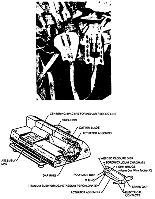
The reefing cutters specifically developed for the Apollo parachutes were highly reliable and of exceptional quality; however, nothing could be done to decrease the temperature sensitivity of the time train. Table 6-8 lists the time variation of the 10-second Apollo reefing cutter as a function of temperature. These data are taken from Northrop Ventura test memo 2211/67-74, dated 8 November 1967.
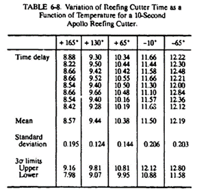
An analysis of test data on the Apollo reefing cutter indicated the possibility of a 1.1-second time difference in the 10-second second-stage cutters for the three Apollo main parachutes. To obtain uniform cutter firing, an investigation was conducted on firing the reefing cutters with an RF signal from the command module. This approach is described in Reference 6.51.
Firing the cutters by RF signal opened another possibility. The weight of the command module during the development cycle increased by 60% with no allowable increase in total parachute force taken by the command-module hard points. Electronic disreefing makes it possible to stagger disreefing of the three main parachutes, increasing the opening force of the first parachute to disreef, but decreasing the combined parachute force to be taken by the command-module hard points.
6.5.4 Special Reefing Concepts
6.5.4.1 Continuous Disreefing
As discussed in section 5.6.6, continuous disreefing is a method where the inflation of the canopy is controlled so as to produce a more-or-less constant or controlled parachute opening force. Many proposals have been made and prototypes have been tested. However, no practical solution has evolved so far.
6.5.4.2 Fixed Reefing by Pocket Bands
The aerodynamic effects of decreasing the inflated diameter of a slotted canopy by using pocket bands are explained in section 5.6.9. Decreasing the inflated diameter should increase stability, especially in the wake of a large forebody.
The mechanics of this process are explained by the example cited in section 5.6.9 (Figure 6-51). The effective porosity of a 6.8-foot-diameter parachute was increased from 26 to 33% by reefing the 6.8-foot-canopy diameter to the equivalent of a 6-foot diameter canopy. Using the terminology from Figure 6-51, the skirt circumference of the 6.8-foot-diameter 16-gore canopy obtained by 16(2 ex + La) is reduced to the skirt circumference of a 6-foot-diameter canopy, or 16(2 ex1 + La1). The free length of the pocket band, La, is calculated for the 6-foot canopy and fastened to the 6.8-foot canopy at the distance, ex1. This arrangement greatly increases the length, Lb1, thereby restricting the skirt circumference, 16(2 ex1 + La1), to that of the 6-foot-diameter canopy and increasing the ratio of air leaving the canopy by the slots to the air going into the canopy at the skirt. Table 6-9 gives actual data for the fixed reef 6.8/6-foot canopy.
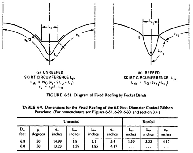
6.5.4.3 Overinflation-Control Line (OC Line)
The OC line prevents overinflation of the parachute canopy by placing a line around the canopy skirt. The line permits the canopy to inflate fully, but restricts further inflation. The line can be a reefing line run through rings in a process similar to skirt reefing. A simpler approach is to fasten the line to the confluence point of suspension lines and radials at the skirt of the canopy. The effects of the OC line on limiting the parachute opening force are discussed in section 5.6.9.
6.6 DESIGNING AND FABRICATING IN TEXTILES
The laws of mechanics and aerodynamics apply to the performance and stress analysis of parachute recovery systems. However, the textile fabrics used in parachute construction have distinctly different mechanical and environmental characteristics than metals or composites. It is not the purpose of this manual to provide a detailed analysis of the complex area of textiles and fabrics, but rather to provide the parachute designer with a cursory survey of the textiles used in the design and manufacture of parachute assemblies. This section discusses the various processes of producing the fabrics and the mechanical and environmental properties of the fabrics. It also provides a list of the most frequently used Federal and military specifications, and presents feedback information on how to design parachutes that can be economically manufactured without problems in the manufacturing process.
The following references provide further information on textiles, designing in textiles, and the equipment and processes used in parachute manufacturing. References 2.17 and 2.18, two of the University of Minnesota short courses on parachute technology, contain extensive lectures on parachute textiles, including textile properties and the spinning, weaving. and braiding process of manufacturing fabrics. Reference 2.21, the Roxboro Seminars on Parachute Manufacturing, discusses the entire field of textiles; new materials; parachute hardware; manufacturing machinery; Government inspection, quality control, and configuration management; the role of computers in the manufacturing process; and related subjects. However, no papers are available on the sequential process of manufacturing a parachute, because parachute companies consider this proprietary information. DuPont and Cellane companies have extensive literature on materials and fabric used in the manufacture of parachutes (Reference 6.52).
6.6.1 Textile Materials
The two primary groups of textiles are those of natural fibers and those of man-made fibers. Fiber is a generic name that refers to all materials used in the manufacture of textiles. Natural fibers include wool, cotton, silk, hemp, flax (linen), and many others. Only silk and cotton are of interest to parachute designers.
Man-made fibers are classified by their origins. Mineral fibers, the only nonorganic fibers, include glass fiber and metal thread used in woven metals such as metal shielding for electrical wiring. All other man-made fibers are based on cellulose, protein. or resin composites. The cellulose group includes rayon; the protein and resin groups include nylon, dacron, Kevlar, and others. Cellulose, protein, and resin are referred to as organic fibers.
6.6.1.1 Natural Fibers
Silk: Silk is produced by the silkworm, which spins a cylindrical cocoon from a thread less than 1/1000 of an inch in diameter, 800 to 1500 meters long, and triangular in cross section. Because the thread is so small in diameter, five to ten cocoons are unwound simultaneously and their threads spun together using the natural glue of the thread. The thread is then spun into yarn and woven into cloth. Silk is the strongest of all natural fibers, resists heat, and burns only as long as a flame is applied to it. The silk fiber is referred to as a long staple fiber, unlike cotton and wool, which are short staple fibers. Table 6-10 shows the characteristics of different materials.
Cotton: Cotton is a natural fiber 0.5 to 2.5 inches long depending on type and country of origin. The cotton fiber is irregular in shape and has a natural twist that makes it extremely suitable for fine yarns and for the fabrication of a large variety of textile fabrics. Cotton is abrasion resistant and is used in parachute assemblies for deployment bags, buffers, and friction-preventing items. All natural fibers can absorb a considerable amount of water without losing strength, but unless treated, they are affected by fungus, bacteria, and insects. Cotton burns without melting and loses 50% of its strength at a temperature of about 350o F.
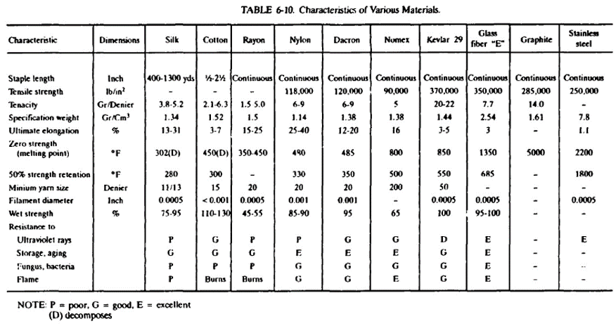
6.6.1.2 Man-Made Fibers
Rayon: Rayon, the oldest man-made fiber, has a cellulose base that makes it economical to manufacture. Rayon has about half the strength of silk or cotton, loses 40% of its strength when wet, burns easily without melting, and decomposes at about 450o F. Rayon was used during World War Il for cargo parachutes but is seldom used today for parachute assemblies.
Nylon: Nylon, developed shortly before World War Il by DuPont for use in clothing, has become the primary fiber for many parachute fabrics. Nylon is a synthetic resin (polyamide) with high tenacity caused by long, highly oriented molecules and high intermolecular forces that resist slippage. Nylon tenacity ranges from 2.5 to 9.5 grams per denier; its elongation ranges from 29 to 40%. Nylon type 6.6, used for parachute fabrics, is rated at 6.6 grams per denier, approximately equivalent to a tenacity of 115,000 lb/inch2, which compares favorably to other materials used in the aerospace industry. Figure 6-52 shows tenacity in grams per denier for a variety of industrial yarns. Nylon is abrasion resistant, durable, and little affected by humidity, fungus, bacteria, organic solvents. and alkalies. Nylon is sensitive to ultraviolet radiation (sunlight); this sensitivity can be reduced but not eliminated by appropriate treatment of the fabric. Nylon melts when subjected to fire but does not burn. This fabric can be used, with little loss in strength, at temperatures of up to 250o F (Table 6-10 and Figure 6-53). Nylon loses 50% of its strength at about 330o F, becomes sticky at higher temperatures, and melts at 480o F. If subjected to repeated stresses, nylon exhibits a certain hysteresis in its strain characteristics, but fully recovers after a few minutes. However, long exposure to high stresses and high temperatures notably decreases the strength of the fabric. See Reference 2.21 for more information.
Dacron: Dacron is a polyester-based man-made fiber with characteristics somewhat similar to nylon, but dacron requires more treatment for good stability. Dacron has somewhat lower elongation than nylon but has better temperature characteristics and better resistance to nuclear radiation. Dacron has better low-porosity stability, more stable elongation for control lines, and slightly less weight and volume than nylon, characteristics that have made this material attractive for sport parachutes.
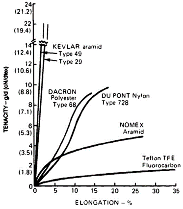
Teflon: The fluorocarbon fiber, Teflon, can be used at temperatures up to 450oF. Its low friction coefficient when in contact with other textile materials is Teflon's outstanding characteristic. Teflon is used as deployment-bag liner and as buffer material where high-speed contact between two nylon components of a parachute assembly may cause friction burns.
Kevlar: The para-aramid fiber, Kevlar, has become very prominent as high-tenacity material for parachute assemblies. Section 6.6.5 discusses Kevlar material and its application for parachutes.
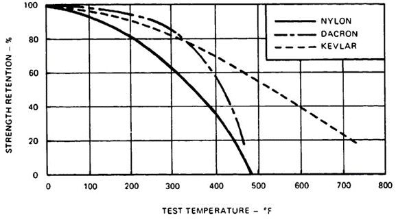
6.6.2 Spinning and Weaving of Textiles
6.6.2.1 Spinning
Figure 6-54 shows a typical spinning process for man-made fibers. A spinning solution is formed of the basic material and then extruded through a number of very fine holes in the spinneret. The fine fibers (called filaments) are combined to filament yarns by twisting the fibers together, or by a glueing process called rotoset. The melt-spinning process shown in the figure is used for nylon, dacron, and glass fiber yarns. Related spinning processes are used for Kevlar, Nomex, rayon, and acetate yarns.
In the spinning process, fibers and yarns may be subjected to twisting, drawing, heat and chemical treatment, and other processes for obtaining desirable characteristics. Nylon filaments, for example, are cold-drawn to four to seven times their original length to create a certain molecular orientation and increase tenacity.
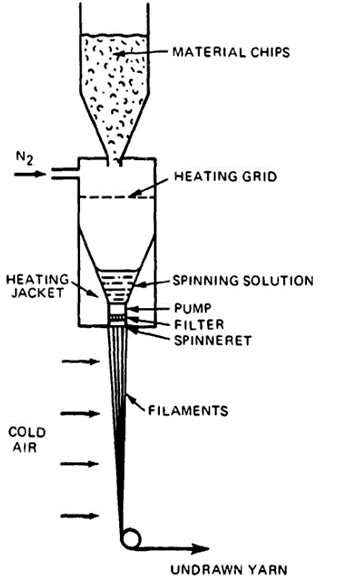
Yarns are twisted together to obtain yarn stability and firmness and to improve mechanical characteristics of the yarn. Twist in yarn is defined by the number of twists per inch (TPI) and by the direction of the twist (Figure 6-55). A Z twist, shown in Figure 6-55 (a), is a right-handed, clockwise twist, An S twist, shown in Figure 6-55 (b), is a left-handed, counterclockwise twist. Figure 6-55 (c) shows Z-twist filaments twisted into an S-twist yarn. In addition to inducing stability and improving mechanical characteristics, twists can greatly change and improve the appearance of fabrics.
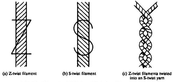
The size and strength of filaments and yarn is most frequently defined by a denier number; a denier is defined as the weight in grams of a fiber 9000 meters long. Although several other yarn-numbering systems are in use, the denier system is the one most frequently used for yarns in parachute fabrics.
6.6.2.2 Fabric Weaving
All fabrics are produced on weaving machines called looms. The fabric produced on a loom has long yarns in the longitudinal direction of the fabric that are called warp. Yarns called fill are woven into the warp at a 90-degree angle.
Three types of looms are in use today. The shuttle loom uses a wooden bobbin to shuttle the fill yarn back and forth through the warp yarns that are fed into the loom from a large spool. This process produces a continuous fill yarn and a firm selvage edge on the fabric. The maximum bobbin speed is about 120 fill threads per minute.
In recent years the rapier and the water-and-air jet weaving processes have been introduced. The rapier process pulls a fill thread by two needle-type rods from each side of the material through the warp threads and cuts the fill thread at each end at a speed of 400 fill threads per minute.
The water-and-air jet process shoots 800 to 1200 individual fill threads through the warp per minute. The economic advantages of the rapier and water-and-air-jet weaving processes are obvious.
Parachute fabric is woven in 36-, 48-, 60-, and 72-inch widths. A typical parachute fabric has 122 warp threads, called ends, per inch width, resulting in 4392 ends for 36-inch material. The warp ends are wound on a spool called a beam. The warp ends are guided through the loom using several devices for straightening, lifting, and lowering the warp threads in preselected groups before inserting the fill thread. The sequence of lowering and raising the warp groups and inserting the fill thread determines the type of weave. The most common weaves are plain weaves where one fill thread goes over and under one warp thread, and the more complex are twill, taffeta, satin, and other weaves.
The type of weave desired is shown in a weave pattern in Figure 6-56. The black squares indicate the thread on top, and the white squares the thread on the bottom. The warp threads are called ends, and the fill threads are called picks. The pattern in Figure 6-56 (a) shows the weave pattern for a plain weave with one end going over and under one pick, and so on. Frequently the selvage edge of the fabric may have a slightly different pattern to ensure a more rigid, form-preserving edge.
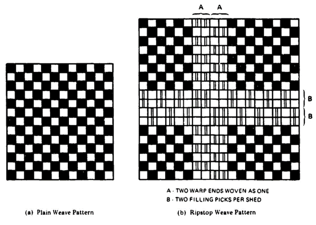
Figure 6-56 (b) shows the weaving pattern for 1.1-oz/yd2 ripstop nylon of MIL-C-7020, the material used in most military personnel parachutes. This fabric has a reinforcing rib woven in to stop small rips and prevent new rips from starting.
6.6.3 Parachute Fabric Specifications
The Department of Defense and other Government agencies have written specifications for all types of parachute fabrics. These specifications define the type of fabric (such as cloth, tapes, or lines), the mechanical properties, the weaving pattern, treatment during weaving, the finishing process, and inspection and testing procedures to ensure compliance with the specification requirements. Reference 2.1,the USAF Recovery Systems Design Guide; Reference 2.21, Piedmont Technical College on Parachute Manufacturing; and the Poynter Parachute Manual, Reference 2.22,list most of the parachute fabric specifications that would be sufficient for preliminary design. For final fabric selection, the specifications should be consulted.
This manual provides a current list of parachute fabric specifications but does not provide technical details.
6.6.3.1 Parachute Cloth
MIL-C-7020, cloth, parachute nylon (includes the standard 1.1 oz/yd2 ripstop)
MIL.C-7350, cloth, nylon. cargo parachutes (medium weight)
MIL-C-8021, cloth, parachutes, nylon, cargo and deceleration (heavyweight)
MIL-C-498, clothe nylon (lightweight)
MIL-C-19262, cloth, nylon or rayon
MIL-C-7219, cloth, duck, nylon
MIL-C-3953, cloth, duck, nylon
MIL-C-26643, cloth, nylon, marquisette (pilot-chute vanes)
MIL-C-3395, cloth, netting, nylon (marquisette)
LP/P DES 81-1A, cloth, nylon, low porosity, US Forest Service Specification used in low porosity hi-glide parachutes
F-111, low-porosity cloth, nylon, G. Harris Corp.
MIL-C-5646, cloth, airplane, cotton
MIL-C-4279, cloth, cotton
CCC.D-419 cloth, duck. cotton, 12.28 oz./yd2
SS 323244, polytetraflouroethylene cloth (Teflon), Sandia specification. For Kevlar fabrics see section 6.6.5.3.
Low-porosity dacron cloth for sport jumper hi-glide parachutes is furnished by FWF Industries.
6.6.3.2 Thread
MIL-T-7807, thread, nylon, Fed. spec. No. VT295
MIL-T-5660, thread, cotton, Fed. spec, No, VT276
MIL-T-43636, thread, nylon, nonmelting
VT285, thread, polyester (dacron)
VT301, thread, silk
MIL-C-4635 and MIL-P-7567 discuss relationship of thread size, stitches per inch, and type of stitching.
6.6.3.3 Parachute Suspension Lines
MIL-C-5040 cord, nylon, cover and core line
MIL-C-7515, cord, nylon, coreless braided
MIL-C-17183, cord, nylon, braided tubular, spliceable
MIL-C-83243, cord, aromatic polyamide, nonmelting (Nomex)
Braided dacron suspension lines are available from FWF Industries.
For specifications for Kevlar lines, tapes, and webbings, see section 6.6.5.3.
6.6.3.4 Webbing and Tape
MIL-W-4088, webbing, textile, woven nylon
MIL-W-5038, webbing and tape, textile, reinforced nylon
MIL-W-27265, webbing, textile, woven nylon
MIL-W-5625, webbing. textile, nylon tubular
MIL-W-17337, webbing, textile, woven nylon
MIL-W-83144, webbing, textile, woven nylon, rolled selvage edge
MIL-W-83279, webbing, nylon
MIL-T-5666. tape, textile, nylon, multiple tubular
MIL-T-8363, tape and webbing, nylon
MIL-T-6134, tape, nylon
MIL-W-9049. webbing, textile, nylon, locking loop
MIL-W-5665, webbing, cotton
MlL-W-530, tape, cotton
MIL-W-5661, tape and webbing, textile, woven reinforced cotton
MIL-W-25339, webbing, polyester (dacron)
Ribbon for ribbon parachutes:
MIL-T-5608 tape, textile: webbing textile
SS 333416, ribbon, tape, and webbing; textile; nylon; Sandia specification
6.6.3.5 Related Specifications
MIL-STD-1520, Corrective action and Disposition System for Nonconforming Materials
MIL-STD-1525, Verification listing of Parachute Textile Materials
6.6.4 Designing in Textiles
Textile fabrics differ in several ways from other materials used in the aerospace industry. Textiles, as a rule, have a much higher elongation, are very flexible, and cannot be machined to a desired shape or cross section. The smallest building unit, the thread, already consists of a multitude of fibers. These characteristics introduce many design aspects not found in other materials.
6.6.4.1 Measuring Textiles
A metal rod has a length that can be measured with a measuring tape, and several people, even under different environmental conditions, will measure the same length. However, several people measuring the same piece of narrow or wide fabric at the same or different geographic locations will arrive at different dimensions, because textiles change in length depending on hand tension and environmental conditions. For this reason, a preload must be defined for measuring the lengths of different textiles. Although parachute canopy cloth is spread out on the cutting table and measured and marked under hand tension, all lines and tapes are measured under a preload. A preload of 1% of the ultimate material strength is required to align all fibers in the woven or braided material before the individual fibers are stretched.
Military specifications, as a rule, comply with the 1% preload but limit the preload to a 5-pound minimum and a 40-pound maximum (see specifications MIL-P-25716 and MIL-C-6635).
Preloads up to 100 pounds are used for high-strength suspension lines on heavy-duty ribbon parachutes.
It is practical to let all fabrics relax for a short period after rewinding from the storage spool before measuring the material.
When NASA people found differences in the length of the same types of Apollo main parachute suspension lines measured at facilities in Southern California and Cape Kennedy, air conditioning was requested at all facilities. This was probably not necessary since all fabrics will elongate and contract about the same amount under similar atmospheric conditions.
6.6.4.2 Changes in Fabric Dimensions Caused by Sewing
Two pieces of wide fabric sewn together will become shorter in the seam than in the unsewn part of the fabric. This length change, shown in Figure 6-57, is called "take-up." The amount of take-up varies with the thickness of the fabric, the number of fabric layers in the seam, the number of rows of stitching, the size of the thread, the stitches per inch, the tension in the thread, and other factors. The take-up may range from 2% for lightweight fabrics connected with a simple fell seam to 10% for the radials of small, heavy ribbon parachutes with multiple radial ribbons and tapes and multiple rows of stitching.
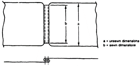
6.6.4.3 Finished Versus Pattern Dimensions
The shrinkage in fabric caused by sewing is somewhat similar to the shrinkage of metal castings when they are cooled. The design engineer must take the shrinkage into account.
All dimensions of a parachute assembly that are measured along a seam will shrink from the pattern dimensions. This shrinkage primarily affects radial seams, vent, skirt, and lateral tapes, and especially the radials of heavy ribbon parachutes with suspension lines sewn over the canopy with multiple rows of stitching.
Radials where the suspension lines run in channels through the canopy and are only attached at the vent and the skirt are less affected by this change.
The designer can specify the finished dimensions or the pattern dimensions, but not both. If finished dimensions are specified, then all pattern dimensions are reference dimensions. The ribbon parachute specification, for example, defines the finished length of the radials, and states that a certain amount of horizontal ribbons should be equally spaced in a finished distance, and defines the horizontal ribbon width and spacing only as reference dimensions.
A decision must be made for every parachute system whether it and its components, and which components, are to be manufactured to pattern or to finished dimensions.
Finished dimensions are necessary for parachutes that must have a repeatable precise aerodynamic performance (such as ordnance and aircraft landing deceleration parachutes). Air vehicle recovery parachutes, cargo parachutes, and most personnel parachutes used with a variation of loads and resultant rates of descent can accept less stringent tolerances. Pattern dimensions may be suitable for these types of parachute assemblies if the finished dimensions are held in acceptable tolerance limits.
6.6.4.4 Fullness
The designer of a parachute canopy may have established the geometric dimensions; for example, for the length of the radial seam. If the designer now adds a small amount of length to this dimension, the added material is called "fullness." Fullness serves two purposes: it creates a certain amount of stress relief in the canopy material, and it ensures that loads are carried in such primary load-carrying members as tapes and radials and are not being transferred to the canopy material. Sections 6.4.5 and 7.3.8 describe how adding fullness to the vent tape and then gathering it to the basic dimensions will create a certain amount of curvature to the canopy vent area, and will result in stress relief in the canopy fabric. The same is true for other parts of the canopy, as shown in Figure 7-12. Recommended amounts of fullness for solid material, circular canopies are 5% for the vent tape, 1% for the skirt tape, and no fullness for the radials.
The second purpose for fullness is to ensure that the main forces in the canopy are carried by the radials, the skirt, and vent tapes and are not being transferred to the canopy cloth. This is especially important for canopies with suspension lines or radial tapes sewn to the full length of the radial seam, and to canopies with cloth in block construction. If checks indicate that the elongation of the radials or tapes is higher than the elongation of the canopy fabric, negative fullness in the radials and tapes or positive fullness in the canopy material must be added.
To obtain load relief in the vent tapes, a common practice is to make the vent lines 5% shorter than the measured diameter of the completed vent. This diameter should be measured after the canopy is completed, since the bunching of material in the vent connected with the multiple rows of sewing causes deviations from the drawing dimensions, especially on heavy-duty ribbon parachutes.
6.6.4.5 Tolerances
Several MIL specifications define the following tolerances for finished parachute parts:
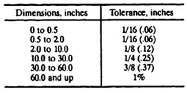
These tolerances have been satisfactory for personnel and cargo parachutes. However, they have caused problems on large parachutes for missile and booster recovery, and have been proven totally inadequate for the Apollo main and drogue parachutes.
It has been proven impossible to comply with a tolerance of 1/16 to 1/8 of an inch between radial centers on heavy-duty parachutes with radials 2 to 3 inches apart at the vent. On this type of parachute, the diameter of the vent should be the critical dimension.
The Apollo main parachutes had suspension lines 1440 inches long. Applying the 1% rule would have permitted a line variation of ± 14.4 inches, or 29 inches between two adjacent suspension lines. The distance between two adjacent lines in the first reefing stage was 4 inches. This presented the unacceptable possibility that the reefing line could zig-zag in a 4-inch skirt distance up to 29 inches in the radial distance. In addition, the 29-inch length difference between two adjacent lines could create a dangerous stress concentration in the canopy skirt area. The allowable length difference between two adjacent Apollo suspension lines, therefore, was limited to 5 inches. The recommendation is to limit the free length of suspension lines in large parachutes by splitting the required total line length into (1) strictly a suspension line, and (2) a suspension line/riser part, as shown in Figure 6-29a.
In cooperation with NASA. a new system of tolerances was developed along with the definition of critical and noncritical dimensions. Critical dimensions as agreed upon included length of suspension lines, radials, vent diameters, length of skirt, vent and lateral tapes, and all leading and trailing edge ring dimensions. The tolerance system jointly agreed upon between Northrop, DCAS quality control personnel, and NASA is shown in Figure 6-58.
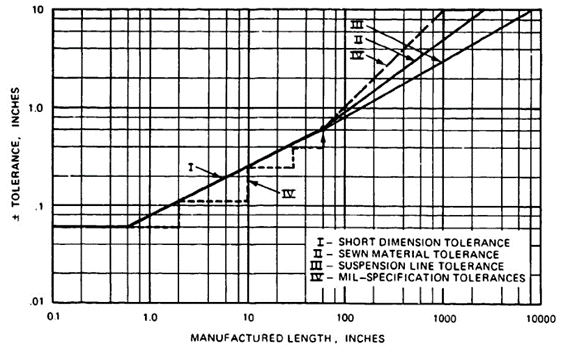
Small dimensional inaccuracies in large canopies with many gores can cause such canopy anomalies as canopy infolding. The Gemini spacecraft astronaut capsule used an 84-foot-diameter, 72-gore, ringsail main descent parachute. A slide rule error of 0.6 inch in the trailing edge length of one of the 13 rings resulted in a surplus length in that ring of 43.2 inches and caused infolding of two canopy gores. A NASA aerodynamic study to find the reason for canopy infolding was terminated when the dimensional error in the gore design was found, corrected, and no more infoldings occurred.
6.6.5 Designing in Kevlar
6.6.5.1 General Information
Kevlar is about 2.5 to 3 times stronger than nylon and is considerably more heat resistant. Hybrid parachutes using nylon canopies and Kevlar suspension lines, risers, and canopy tapes will save up to 40% in weight and volume, depending on the amount of Kevlar used. Depending on the type of fabric, Kevlar may also be 5 times more expensive than nylon, and is not available in the wide range of fabrics as is nylon, especially not in lightweight, wide fabrics. New developments in lightweight, wide fabrics were recently reported in Reference 6.53. The superior strength/volume characteristics make Kevlar extremely attractive for application where strength and volume requirements outweigh higher cost.
The Sandia National Laboratories in Reference 6.54 summarizes its experience in the use of Kevlar for all types of parachute application, placing emphasis on heavy-duty ribbon parachutes. Using Kevlar on heavy-duty ribbon parachutes for suspension lines and all canopy reinforcing elements, such as radial tapes, vent, and skirt tapes and vent lines, reduces the parachute weight and volume by 25 to 40% depending on the amount of Kevlar used. All-Kevlar ribbon parachutes were designed and tested, but Sandia decided, for the present, to use nylon canopies in connection with Kevlar suspension lines and canopy reinforcements. Kevlar ribbon canopies require considerable redesign because of the low elongation of Kevlar combined with sewing problems. Sandia also has successfully designed and tested large, lightweight, solid-fabric parachutes with Kevlar suspension lines and canopy reinforcements. Again, a weight and volume saving of 25 to 40% was achieved. This agrees well with the experience of the parachute industry.
The Naval Surface Warfare Center at Silver Spring, Md., replaced a nylon cross parachute for a low-altitude, 500-knot ordnance device with an all-Kevlar cross parachute. The Kevlar parachute required only 40% of the volume of the nylon parachute. However, new wide fabrics had to be developed for this application (Reference 6.55).
The Air Force, in Wright Aeronautical Laboratories at Wright Patterson AFB, investigated the use of Kevlar for ribbon parachutes. The investigation included the development of suitable fabrics, the design and manufacture of Kevlar ribbon parachutes, and the testing of the parachutes in high-speed airdrops. Reference 6.56 covers this investigation. Department of Defense agencies, the Sandia National Laboratories, DuPont, and the parachute industry have provided information on Kevlar and Kevlar applications in parachutes for this manual.
6.6.5.2 Kevlar Material
Kevlar was developed by the DuPont Co. Kevlar was originally to be used as a replacement for steel wire in automobile tires. Two Kevlar types, Kevlar 49 and Kevlar 29, have been used increasingly in the aerospace industry. Kevlar 49. with a tenacity of up io 23 grams per denier and a low elongation of 2 to 3%, is used extensively in high-strength composite structures for air vehicles, ground vehicles, boats, and for similar applications (Reference 6.57).
Kevlar 29, with a slightly higher elongation of 3.5% and a more flexible fiber, is used in high-strength textiles, including wide and narrow parachute fabrics. A Kevlar yarn consists of a large number of filaments extruded from an acid solution using a process slightly different from that for nylon. The individual fibers are held together by cohesion and natural glue. Later, the fibers are rotoset or twisted to enhance weaving capability. Twisting provides the yarn with firmness and stability and contributes to yarn strength up to a certain number of twists. The low elongation and firmness of the individual fiber require different methods of weaving and braiding than those used for nylon fabrics. The ratio of fabric strength to original yarn strength on Kevlar is about 70 to 90% compared to nylon, which obtains a yarn-to-fabric strength ratio of up to 100% (Reference 6.58).
Table 6-10 compares materials used in the aerospace industry with those used for parachute fabrics. The high tenacity of Kevlar of 22 to 23 grams per denier (shown in Figure 6-52) as compared to nylon with 6 to 9 grams per denier, is Kevlar's most outstanding characteristic. Figure 6-53 shows that Kevlar maintains about 55% of its strength at the melting point of nylon.
Figure 6-59, taken from Reference 6.56, shows the effect of twist on the tenacity of Kevlar yarn. Kevlar, similar to nylon, is affected by ultraviolet radiation. Figure 6-60, taken from an NWC investigation, Reference 6-59, shows the loss in strength caused by exposure to sunlight.
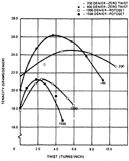
The lightest commercially available Kevlar yarn of 200 denier does not permit weaving a lightweight fabric that can compare with the widely used 1.1 oz/yd2 nylon ripstop fabric. However, the recently introduced 55-denier Kevlar yarn has been woven into lighter fabrics (Reference 6.57).
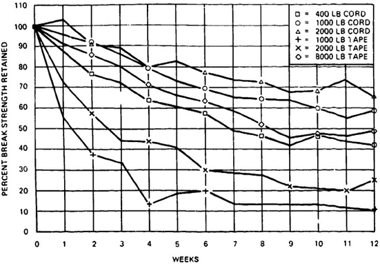
6.6.5.3 Kevlar Material Specifications
Parachute Cloth
MIL-C-8156, cloth, parachutes, aramid, intermediate modulus
MIL-C-38351, cloth, parachutes. aramid, low modulus
Thread
MIL-T-87128. thread, para-aramid, intermediate modulus
Suspension Lines
AMS 3814, cord, coreless braided, para-aramid, intermediate modulus
MIL-C-38282, tubular webbing, para-aramid, low modulus
Webbing, Tape
AMS 3793, tape, webbing textile, para-aramid, intermediate module
Sandia National Laboratories Specifications
SS 323279, cloth, textiles, Kevlar-aramid, intermediate modulus
SS 323241, tape and webbing, textiles, Kevlar-aramid, intermediate modulus
SS 323243, thread, textiles, Kevlar-aramid, intermediate modulus
SS 373117, waxing process, Kevlar and nylon thread
6.6.5.4 Design and Fabrication
Experience gained in the design and fabrication of all-Kevlar or Kevlar-nylon hybrid parachutes is discussed in References 6.57, 6.58, 6.59, and in several lectures of the Roxboro Parachute Manufacturing Seminar, Reference 2.21. General experience gained in the design and fabrication of nylon parachutes applies equally well to designing and manufacturing in Kevlar. However, the special Kevlar characteristics of low elongation and high strength require certain adjustments and changes, especially on parachutes manufactured entirely from Kevlar.
Hybrid parachutes using nylon canopies and Kevlar suspension line, canopy reinforcing tapes, and radials have been used successfully for several applications with savings in weight and volume of 25 to 35%.
Parachutes manufactured totally from Kevlar do not have the benefit of stress normalization and load relaxations as do bias-constructed, high-elongation nylon canopies. Because of this, a stress-oriented design with special attention to the interface between canopy fabric and the load-carrying canopy tension members, radials, skirt, and vent tapes and vent lines is required.
Hybrid nylon-Kevlar canopies are best sewn with nylon thread, whereas Kevlar thread should be used for all-Kevlar canopies.
Low-elongation Kevlar lines are well suited for control lines, reefing lines. and for elements that require good dimensional stability. Indications are that Kevlar suspension lines decrease the rotational tendencies of cross parachutes.
The abrasion of Kevlar has been a controversial subject. Reference 6.60 and reports from the field rate Kevlar as the same or slightly better than nylon. High-speed extraction of Kevlar parachutes from deployment bags indicates that Kevlar parachutes suffer less from friction burns.
Kevlar seams in wide fabrics are less firm than nylon seams and have a tendency to pull out in a "rake type" fashion. To counteract this fault, Kevlar cloth can be slightly coated. The coating makes the cloth easier to work with and produces better seams. For uncoated fabrics to make a firmer seam, a binder such as sergine or a similar solution should be used in the seam area. In Reference 6.61, seam efficiencies of Kevlar cloth using different seams, stitching, rows of stitches, and type of sewing were investigated. Kevlar seam efficiency is low compared with nylon, and more rows of stitching and longer stitch patterns are required for Kevlar.
Chinese finger splicing is possible with Kevlar lines; however, the length of the insert should be equal to 15 times the line diameter, instead of 10 times the line diameter as on nylon.
The same preloads can be used for Kevlar lines and tapes as for nylon. Kevlar cannot be hot cut with electric knives and standard cutters, and scissors require frequent sharpening. Special cutter blades and scissors are commercially available.
Sewing machines used for nylon fabrics are also used for Kevlar; however, thread tension needs adjustment to avoid damage to sewing machine parts by the strong Kevlar thread.
6.7 PARACHUTE RECOVERY SYSTEM WEIGHT AND VOLUME
6.7.1 Importance of Minimum Weight and Volume
A precise determination of the necessary parachute weight and volume is important early in any air vehicle development program requiring parachutes.
The relationship of weight and volume can be expressed by the amount of parachute weight that can be packed into 1 cubic foot of volume. This introduces the importance of pressure packing. The higher the pressure, the more weight can be stowed in a given space. Handpacked parachutes, such as those used for sport parachutists and personnel parachutes used for aircraft escape, stow about 22 to 23 pounds in I cubic foot of volume. Pressure-packing combined with suction to remove entrapped air can increase pack density to close to 50 pounds of parachute weight per cubic foot of compartment volume.
Hybrid nylon/Kevlar parachute assemblies and all-KevIar parachutes will increase this value slightly because of the 26% higher specific weight of Kevlar. Sandia National Laboratories and industry sources state that packing methods and pack pressures developed for nylon parachutes are directly applicable to Kevlar/nylon and all-Kevlar parachutes.
Three methods for calculating the weight of a parachute or a parachute recovery system are:
- The preliminary design method
- The drawing method
- The TWK method
6.7.2 The Preliminary Design Method
Data on the weight of different types of parachutes and parachute recovery systems, including such components as storage containers, sequencers, and impact attenuation systems, are plotted in Figure 6-61, which shows the percentage weight of a parachute recovery system and its various subassemblies as functions of the primary vehicle weight.
The percentage weight of the parachute recovery system components decreases with an increase in vehicle weight caused by the relative weight decrease of the various components. Another reason for the weight decrease is that parachute recovery systems for larger air vehicles generally have lower permissible parachute forces expressed in g in relation to the weight of the air vehicle.
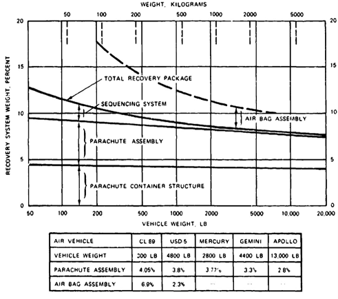
Figure 6-62 plots the weight of three groups of main descent parachutes. The I-curve is valid for extended-skirt and polyconical types of parachutes of all-nylon design deployed in the velocity range of 150 to 200 knots. Using a hybrid nylon/KevIar design will decrease the parachute weight by 25 to 40%.
The data plotted in curve Il refer to main descent parachutes that were deployed at velocities up to 300 knots, such as were used on the B-58 and B-70 crew modules, and may apply to some personnel parachutes used in ejection seat assemblies.
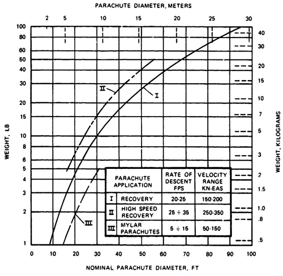
The Ill-curve refers to a series of 0.25-mil mylar parachutes with 100-pound-strength suspension lines. These parachutes were designed for deployment at close to zero dynamic pressure at high altitudes.
These weight figures refer to the parachute itself, without deployment bags, pilot chutes, or other components. As a rule, deployment bags weigh 5 to 6% of the parachute, and deployment bags plus pilot chute and pilot chute bridle add 3 to 5%. First-stage drogue-chute assemblies will weigh from 25 to 40% of the main parachute weight depending on deployment dynamic pressure and riser length. A long riser behind a large-diameter forebody can add considerable weight.
Parachute clusters have 5 to 10% higher weight than a single parachute of equal drag area. This is because of the loss in drag caused by cluster interference (see section 5.10).
Figures 6-63 and 6-64 show the weight of all-nylon ribbon and ringsail parachutes versus diameter and strength range.
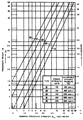
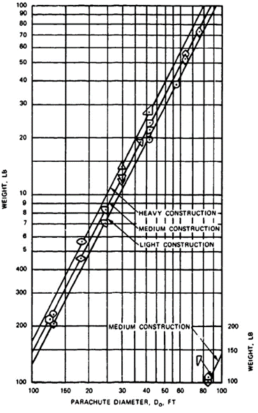
6.7.3 The Drawing Method for Determination of parachute Weight
If detailed drawings with material lists are available, the weight of the parachute assembly can be determined from the material and hardware specifications. Experience shows that this weight is frequently about 5% higher than the weight of the manufactured assembly.
6.7.4 The TWK Weight Determination Method
If no detailed drawing is available, but the primary dimensions of the parachute are known, the following method will give good weight data. The weight of a parachute can be written in the following form:

where:
Wp = Weight of the parachute, lb
So = Surface area of the finished canopy, ft2
Wc = Specific drag surface weight, lb/ft2
Do = Reference diameter of the finished canopy, ft
NG = Number of gores (radials) in the canopy
WRT = Specific weight of radial tape, lb/ft/1000-lb strength
FRT = Strength of the radial tape, lb
NSL = Number of suspension lines
LS = Length of suspension lines, ft
WSL = Specific weight of suspension lines, lb/ft/1000-lb strength
FSL = Strength of suspension line, lb
In this formula Do, So, NG, NSL, LS, FRT, and FSL, are known preliminary design data. The specific canopy weight, Wc, refers to the entire canopy including vent and skirt tape, but not to reinforcing radial tapes. The following specific canopy weights have been evaluated from manufactured canopies:
Canopy material 1.1 oz/y2 1.1 oz/y2 1.1/2.25oz/y2
-----------------------light design standard design combined design
Weight in lb/ft2 0.092 0.105 0.0115
The 1.1/2.25 group refers to canopies where the canopy vent area uses 2.25-oz/y2 as is common on reefed canopies.
The following is the specific weight of suspension lines, webbing, and tapes:
| Woven nylon lines | WSL | = 0.01 lb/ft/1000-lb strength |
| Braided nylon lines | WSL | = 0.0075 lb/ft/1000-lb strength |
| Kevlar lines/webbing | WSL | = 0.0035 lb/ft/1000-lb strength |
The specific weight of lines and webbings decreases with increasing line/webbing strength. A 10,000-pound line has about 20% less specific weight than a 1000-pound line.
Tie weight calculation for suspension lines can be used also for risers using the quoted specific weights for lines and webbings.
For determining the weight of the parachute assembly, the percentage weight values in this section apply.
A method somewhat similar to the TWK method was presented by K. French in Reference 6.62.
6.7.5 Pressure Packing of Parachute Assemblies
The most commonly used methods for reduction in parachute stowage volume are lace-packing and pressure-packing using mechanical or hydraulic presses combined with suction to remove entrapped air, and autoclaving for heat setting.
Lace-packing is best suited for cylindrical compartments using the banana-peel type bags shown in Figure 6-36 and described in section 6.3.5.2. Using leverage-type tools or clam-shell forms with presses allows pack densities of up to 50 lb/ft3.
Air vehicle parachute compartments are frequently semi-rectangular or oddly shaped. An example is the storage area for the Apollo main parachutes that consisted of a quarter section of a truncated cone under the forward heat shield. An air gap of 1/2 inch between deployment bags and the heat shield had to be maintained to prevent heat transfer between the heat shield and the parachutes. Pressure-packing in time intervals and air suction and autoclaving at 180oF for 24 hours was used. For transfer and storage, the parachutes were housed in a wooden form duplicating three sides of the storage area. The parachutes were then wrapped in two layers of plastic sheeting to prevent air entering the packed parachutes. The resultant pack density of 47 lb/ft3 is equivalent to the density of maple tree wood.
Removal of the plastic covers and the opening of the daisy chain bag after 1 year did not result in any movement of the packed parachute; everything remained in the tightly packed position. The suspension lines, after having been extended to their full 120-foot length, snapped back to within 3 feet of their stowed position. The canopy behaved in a similar manner. Subsequent laboratory tests of components and parachute free-flight tests did not reveal any measurable strength degradation.
Early in the program, the heavy pressure-packing bent reefing rings and cutters and caused damage to the lightweight canopy cloth between adjacent reefing rings. Stronger reefing rings, proper cutter and ring location, combined with X-raying every packed parachute eliminated this problem. Since 2007, all-textile reefing loops have been used instead of metallic reefing rings on some systems, eliminating this type of damage and lowering the parachute total weight, Reference 6.93. Figure 6-65 shows the packing presses used for packing the Apollo main parachutes, and Figure 6-66 shows an Apollo main parachute pressure-packed in its wooden storage form and wrapped in two plastic sheets.
Some damage has been seen on the mid-panel fold lines for parachutes packed at a very high density in packing fixtures that contain an angled side. This has been conjectured to be caused by the higher pack density close to the angled side due to the shorter distance between the press plate and the angled side at the edge of the press plate. In other words, there is much more fabric between the center of the press plate and the angled side than at the edge of the press plate and the angled side. No definitive data is available to prove that the damage was a result of this, but awareness of this phenomenon is important when considering fixture design.
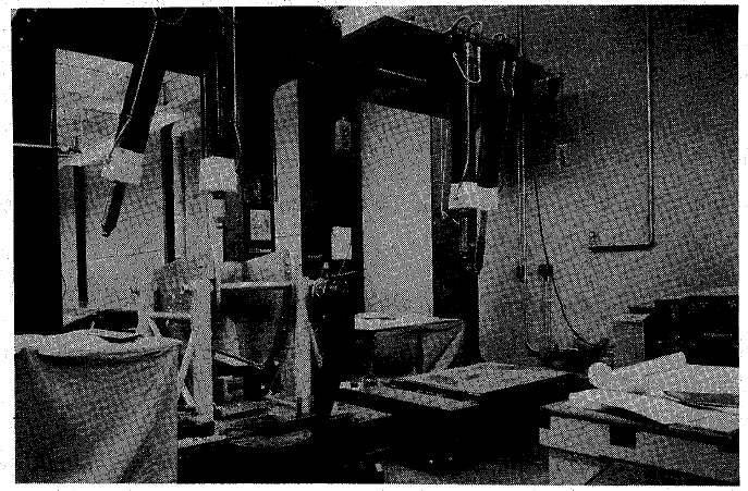
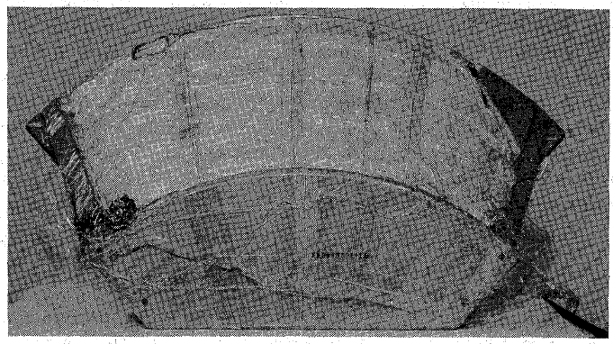
6.7.6 Investigation of Pressure-Packing
The results of an investigation of pressure-packing are reported in Reference 6.63. The investigation found that the relationship of pack density as a function of pack pressure is relatively independent of the form of the packing container or the type of parachute—solid cloth, ribbon, lightweight, or heavyweight. Figure 6-67, taken from Reference 6.63, demonstrates this statement. An investigation of packing time intervals indicated that extending the time under pressure to several days provides a slight reduction in required packing volume, a fact that was later confirmed in the Apollo Program. Figure 6-67 also shows that little is gained by extending the specific pack pressure beyond 200 psi where a pack density of 45 lb/ft3 is obtained. The 47 lb/ft3 pack density on the Apollo parachutes required a specific pack pressure approaching 600 psi.
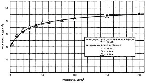
6.8 LANDING IMPACT ATTENUATION SYSTEMS
6.8.1 Landing Analysis
Every parachute landing of a vehicle or load requires that the vertical and horizontal landing energy be absorbed at ground contact. At slow descents and with rugged vehicles or loads, the vertical energy can be absorbed by elastic vehicle deformation and ground penetration, and the horizontal energy can be absorbed by sliding when the load has landed.
The energy to be absorbed at landing is equivalent to the decelerating force, F, acting over the deceleration distance, s, or

(1)
F can be written F = n WS , where WS is the weight of the system to be decelerated and n is the allowable deceleration in multiples of the acceleration of gravity, or n = F/WS . n will be called the allowable deceleration factor.
For most parachute-vehicle systems, the allowable impact deceleration is limited by structural and load considerations. Common practice is to refer to the impact deceleration factor, n, as the allowable deceleration.
The energy, E, to be absorbed at ground contact is E = mVh2/2 for horizontal deceleration, and E = mVv2/2 + WS s for vertical deceleration.
Introducing the system weight ws = mg and the velocity limits, the energy is:
E = [Ws(V12-V22)/2g] + Wg s (2)
Solving for the required deceleration distance, s, and introducing the allowable deceleration factor, n, and the efficiency of the impact attenuator, η, the required deceleration distance (stroke) is:
s = (V12-V22)/[2g(nη - 1)] (3)
Where
s = required deceleration stroke (distance), ft
V1 = rate of descent at start of deceleration, ft/s
V2 = rate of descent at impact (generally zero), ft/s
g = acceleration of gravity = 32.174 ft/s2
n = allowable impact deceleration in multiples of g
F = decelerating force, lb
Wg = parachute-load system weight, lb
η = efficiency of impact attenuator system, dimensionless
The required deceleration stroke depends primarily on the rate of descent, V1, and the allowable impact deceleration, n.
Equation (1) only accounts for the vertical deceleration. Movement in the horizontal plane caused by ground wind, use of a gliding parachute, or parachute oscillation necessitates (a) disconnecting the parachute assembly at ground contact to avoid dragging by the wind and possible vehicle damage, and (b) using an omnidirectional impact attenuator or attenuator arrangement. To predict or control the orientation of vehicles, loads, or platforms at landing has been proven impossible and so makes it difficult to depend on ground sliding in the longitudinal axis of the load. The requirement for an omnidirectional impact attenuation capability rules out certain types of shock absorbers.
The dynamics of the landing process of vehicles or loads with vertical, horizontal, and possibly tumbling motion is complex and dealt with in references 6.64 to 6.66.
6.8.2 Relationship of Deceleration Stroke, Rate of Descent, and Allowable Impact Deceleration
The required vertical deceleration stroke for any kind of vehicle as a function of the rate of descent, V1, and the allowable impact deceleration, n, is plotted in Figure 6.68, using the assumption that the velocity at impact, V2, is zero; and the impact attenuator used has an efficiency η of 0.65, the efficiency value of air bags.
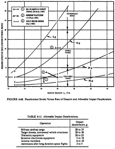
Impact decelerations shown in Figure 6-68 labeled I were measured on the Radioplane OQ-19, a rugged target drone. Data labeled 2 refer to measurements on airdrop cargo platforms.
Figure 6-68 also defines application ranges for certain types of impact attenuators. Crushable and frangible attenuators, such as paper, plastic, and aluminum honeycomb, and metal cutting devices are suitable for required deceleration strokes in the up to 12-inch range. Inflatable air bags are best suited in the 12- to 36-inch deceleration stroke range. Longer deceleration strokes can be obtained with retrorockets. Such attenuators as crushable nose cones, ground penetration spikes, and others have been used successfully for special applications; however, most of these devices have design and application features that limit their operational usefulness.
Allowable impact decelerations based on measured data and experience are listed in Table 6-11.
6.8.3 Selection and Description of Impact Decelerators
6.8.3.1 General
The rate of descent, allowable impact deceleration, type of vehicle, and operational landing condition are the factors that determine need for impact attenuation and the required deceleration stroke. The selection of the impact attenuator best suited for the operation depends on some or all of the following considerations:
Required deceleration stroke
Vertical and horizontal energy absorption requirement
Possible variations in vehicle weight and rate of descent
Energy absorption characteristics of attenuator
Attenuator weight, volume, and stowage conditions
Soil surface condition at landing
Acquisition and life-cycle cost
Reusability and cost of refurbishment
Maintenance, recycling time
Safety and maintenance during flight
Most of these requirements are self-explanatory. Weight and volume of the stored attenuators are of minor importance for military airdroppable cargo, but are of major importance (volume more often than weight) for air vehicles, crew modules, and missiles. Vehicles that are flown only over military test ranges usually land in less rough terrain than vehicles that fly in combat areas. The same can be said for aircrew escape modules that may land in flat terrain, mountains, forests, or water. Reusability, recycling times, and cost are important for target drones and unmanned reconnaissance vehicles, but are not required for airdroppable cargo or aircraft crew escape modules. Rocket fuel and high-pressure storage vessels may be a safety consideration for vehicles that fly in combat areas. Cost is of major importance for airdroppable cargo, but is less important for expensive manned and unmanned air vehicles. For manned air vehicles, reliability is the highest priority. Military airdroppable supplies may trade cost for reliability. Requirements for omnidirectional impact capability eliminate oleo and pneumatic strut type shock absorbers.
An ideal impact attenuator or impact-absorbing material would exhibit the load-deceleration stroke diagram shown in Figure 6-69. All impact attenuators and impact-absorbing materials deviate from this ideal energy absorption characteristic. A typical diagram for a crushable material in the honeycomb group is shown in Figure 6-70. Figure 6-70 demonstrates that an initial force, called the peak force, is necessary to start the compression of the material. The rise of the force curve, called the onset rate in g per second, is important for manned vehicles, since the onset rate is limited for the human body. The peak force determines the design load of the system. A high, steady average crushing force increases the efficiency of the attenuator system. All energy should be absorbed before ground contact. Bottoming out of the attenuator results in a high final peak force. Stored elastic (returned) energy causes the system to bounce.
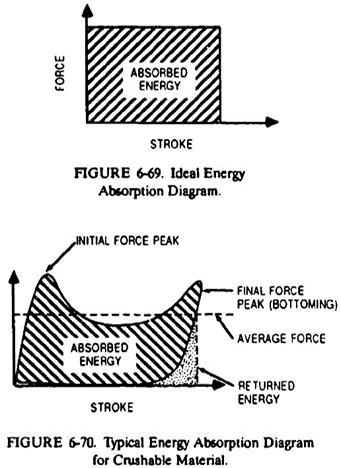
More than 100 reports are available that deal with impact attenuators used in connection with parachute descent systems.
6.8.3.2 Crushable Impact Attenuators
Crushable impact attenuators include paper, plastic, aluminum honeycomb (see Figure 6-71), and several types of foam material. All honeycomb material consists of a cell structure with variation in the cell size and material density. The energy absorption capability is higher in the x-direction, but remains at about 25% in the y-direction. The attenuator is delivered compressed in the y-direction and must be extended and covered with a top and bottom sheet prior to use. The primary application of the crushable impact attenuator is cushioning material for airdroppable cargo platforms that require energy absorption primarily in the vertical plane, with the horizontal energy being absorbed by sliding on the ground. Figure 6-72 shows a cargo platform loaded with a 42,000-pound AM551 armored reconnaissance assault vehicle using multiple layers of paper honeycomb for impact attenuation. References 6.67 and 6.68 detail the use of paper honeycombs for loads on airdrop cargo platforms.
Paper Honeycomb: The energy absorption characteristics of various types of paper honeycombs have been extensively investigated. References 6.69 to 6.71 give some of the results. Figure 6-73, taken from Reference 6.71, shows the stress-strain relationship of MIL-H-9884A paper honeycomb pads used by the U.S. Army for cargo platforms. Ihe figure shows that this type of paper honeycomb can be compressed to about 30% of its height before bottoming out. A small peak force occurs at the beginning of the compression stroke, and a residual elastic force remains at the end of the stroke, which can cause a slight rebound. If the total energy is not absorbed at the end of the 70% compression, a high ground-impact force will occur.
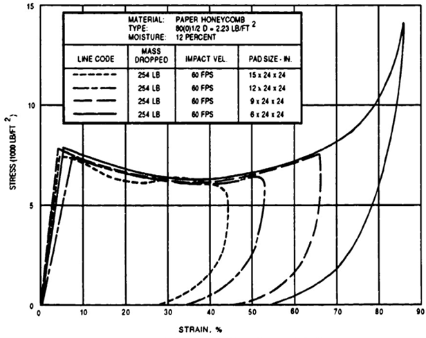
An investigated foldable paper honeycomb design used for military cargo platforms, as shown in Figure 6-74, is described in Reference 6.72.
Aluminum Honeycomb: Extensive investigations of crushable impact attenuators by the University of Texas, described in References 6.69 to 6.71, include aluminum honeycomb materials. The Northrop BQM-74 target drone uses extendable, honeycomb pads for cushioning the impact on land landings.
Foam Plastics: Foam plastics as impact attenuators have also been investigated by the University of Texas (References 6.69 to 6.71). The stress-strain relationship of foam plastic is illustrated in Figure 6-75; taken from Reference 6.68. Foam plastic compared to paper honeycomb has a slightly lower peak force and bottoms out at about 50% of its height. Foam plastics are 100% omnidirectional in their energy absorption capability. Their energy absorption per pound of weight is low; they require relatively large storage volume in the uncompressed state; and they are not reusable.
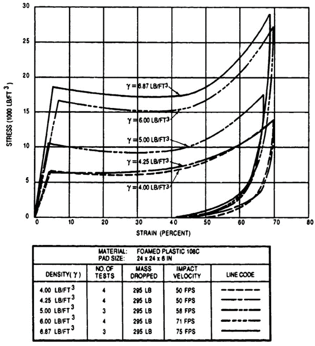
A typical application for foam plastic is its use in cylindrical parachute test vehicles for the cushioning of telemetry and other electronic equipment. The electronic equipment is stored in a longitudinal cavity in the test vehicle and is held in place with light shear pins. A styrofoam pad of 10 to 20 inches in front of the telemetry box is compressed on landing impact and serves as an effective, low-cost shock absorber.
The development of a transparent, omnidirectional shock absorber for an instrument container is described in Reference 6.73.
The Air Force Flight Laboratory at Wright Patterson AFB has investigated a foam-in-place impact attenuator for an unmanned reconnaissance vehicle. An extendable textile bag was attached to the underside of the vehicle and hardening plastic foam components were released into the bag. Hardening of the plastic took about one minute. The development and laboratory testing of this system is described in Reference 6.74. The advantage of this system is its small storage volume that can be located conveniently in the air vehicle. Its disadvantages include extensive plumbing and control equipment and a long, temperature-sensitive foam hardening time.
Figure 6-76 compares the effectiveness of several crushable materials by plotting the required compression force over the effective stroke. In analyzing Figure 6-76, you must remember that the compression stroke as part of total material height is different for the various materials.
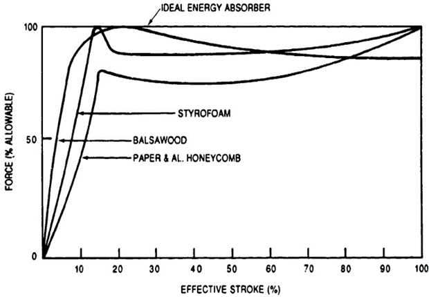
Figure 6-77, taken from Reference 6.75, compares the efficiency of different types of impact attenuators.
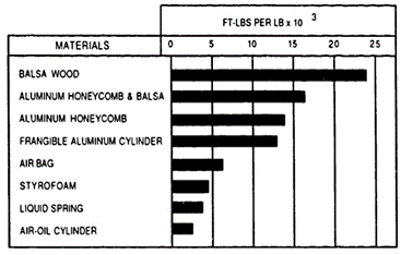
6.8.3.3 Air Bags
Air bags have increased in popularity for the impact attenuation of such air vehicles as target and reconnaissance drones, training missiles, and for the landing of aircrew escape modules. Figure 6-68 defines the required deceleration stroke range of 12 to 36 inches as the range best suited for air bag impact attenuators. Air bags require relatively little storage volume compared to crushables, are reusable, have a high energy absorption capability per pound of weight, and use almost 100% of the compression stroke for shock absorption.
The basic concept of the air bag consists of a textile bag coated with flexible plastic for zero porosity. The bag or bags are stored in the fuselage or wings of the air vehicle. After the main descent parachutes are inflated, the bag compartment cover is ejected, and the bag is deployed and inflated to I to 2 psi to obtain a proper initial shape. At ground contact, the pressure in the bag rises adiabatically. At a predetermined level, pressure relief valves open and allow part of the compressed gas to escape, flattening the pressure force curve for better bag efficiency. Air bags are designed for one specific energy level. Changing the rate of descent, and thereby the energy to be absorbed, results in a bounce at the end of the deceleration stroke if the energy was higher than the design level; or, if the energy was lower than the design level, stopping the vehicle above the ground.
Dual-chamber air bags or small secondary bags have been used to keep the vehicle off the ground in rocky terrain or unsuitable ground conditions.
Figure 6-78 is a typical air bag pressure-stroke diagram. At ground contact, the bag starts to compress and the internal pressure increases until at Point A the pressure relief valves open simultaneously, staggered, or pressure controlled. The pressure increase lessens until the allowable pressure level is reached at Point C. A gradual pressure decay follows.
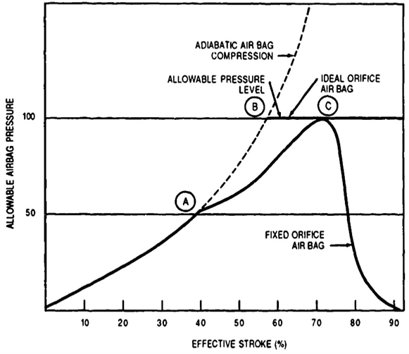
The design of the pressure relief valve (orifice) contributes notably to the efficiency of the bag. Ideal orifices permit the bag pressure to rise to Point B and then remain constant until ground impact. Some recent orifice designs (described later in this section) have increased bag efficiency.
The height of the air bag is determined by the required deceleration stroke. The bag diameter is determined from the relationship that the bag cross section area times the bag pressure is equal to the allowable deceleration factor n times the vehicle weight, or
n Wv=pbSb
where:
n = allowable impact deceleration factor, dimensionless
Wv = vehicle weight, lb
pb = bag pressure, psi
Sb = air bag footprint area, inch2
The vehicle weight and the allowable vehicle deceleration at impact are fixed design values. The bag pressure and the bag cross section are variables and are influenced by the design rule that the bag height should not exceed 1.25 to 1.5 times the bag diameter. Both dimensions again depend on the shape of the bag, the bag design, and the bag installation.
Figure 6-79 shows several operational air bag designs and installations, and Table 6-12 provides technical data on the air bag systems shown in the figure. The air bags for the airdrop platforms were gravity deployed, weighted with lead to enhance bag stretch, and inflated by atmospheric pressure to eliminate the need for a pressurization system. These air bags had a poor initial shape, poor pressure onset rates, and a poor performance in general. All air bags shown have pressure relief valves. Some of the older bags had single-pressure, pop-out diaphragms. The USD-5 reconnaissance drone had diaphragms for two pressure levels. The recent Canadian CL-289 (USD-502) has pop-out sleeve-type pressure control valves detailed later in this section.
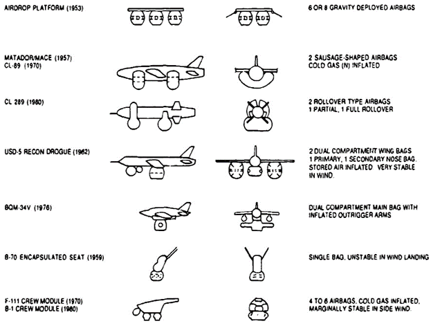
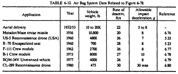
Stability of air bags in wind landings or on an oscillating parachute is a problem. Wind orientation of air bag systems for aligning the long axis of the vehicle with the wind has proven to be impossible. Any side motion must be absorbed by sliding on the ground. Sliding in plowed fields is almost impossible; the dust on dry lake beds acts like a lubricant. Air bags must stay under the vehicle with little deformation. Internal bag cross-bracing is used on the USD-5 bags. The CL-289 uses two pairs of sausage-shaped air bags with the front bag surrounding the vehicle. This arrangement permits a no-damage landing and a quick vehicle turn-around time. The USD-5 uses a wide base for air bag installation, which provides stability in sidewind landing and sliding characteristics. The BQM-34V air bag design has two arms protecting the wing containers. Encapsulated seat bags as used on the B-70 were unsatisfactory in sidewind landings because of the relationship of bag diameter to vehicle height.
Figures 6-80 and 6-81 show two typical air bag valve designs. The Figure 6-80 design was used on the USD-5 dual-compartment air bags. Around the circumference of the air bag are two rows of dual-wall orifices reinforced with steel wire. Into each orifice is inserted a rubber disk with a circular groove. When the internal bag pressure reaches a predetermined level, the rubber diaphragm blows out along the circular groove and reduces bag pressure. It is important to have the valve blow out along the circular groove, thereby providing a controlled opening, rather than having an uncontrolled random blowout.
Figure 6-81 illustrates the variable airflow pressure relief valve used on the CL-289 air bags. The bag orifice is covered by a disk, and a sleeve fabricated from stretch fabric pops out and meters the airflow from the bag. This stretch fabric sleeve opens at high internal pressure and restricts the airflow to a low pressure. Pop-out metal diaphragms are used on the F-111 air bags.
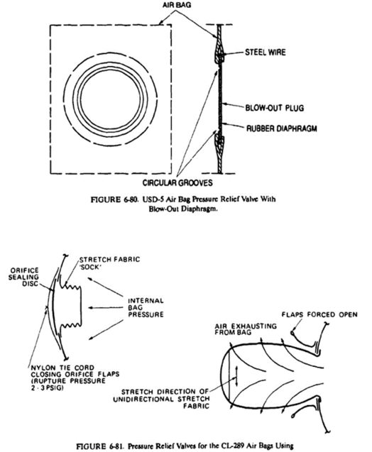
Most air bags are inflated with nitrogen stored in 3000-psi bottles. Nitrogen is available on most air bases. The USD-5 drone used dried air, stored at 3000 psi. Several air bag systems use injector nozzles with a nitrogen-air mixture for inflation of the air bags; this saves considerable weight and volume and minimizes the effects of the temperature drop from the high-pressure storage condition during bag inflation.
6.8.3.4 Retrorocket Landing Attenuation System
Retrorockets may be called long-stroke impact attenuators. Retrorockets are well suited for loads and vehicles that have impact deceleration limits when landing in the 3- to 6-g range that normally results in required deceleration strokes of more than 3 feet. These long deceleration strokes cannot be obtained with air bags or crushable attenuators. Another advantage of retrorockets is their high energy-weight ratio and their capability of decelerating the vehicle before ground contact—a decided disadvantage of air bags and crushables.
The Soviet Union uses parachute systems for land landing their cosmonauts on the South Russian plains. They also use retrorocket parachute systems for the airdrop of heavy military cargo.
The U.S. Army Redhead-Roadrunner target/missile is the only operational parachute retrorocket landing system used in the United States so far. The primary reason for the use of retrorockets as impact attenuators on the Redhead and Roadrunner was the resultant weight saving (Reference 6.81).
The Army Natick Research, Development, and Engineering Center in Natick, Mass., in the 1960s and 70s, funded extensive efforts to develop a retrorocket parachute system for landing heavy airdrop platforms. References 6.82 and 6.83 document this development work.
Many studies and some development work have been conducted by NASA, the Air Force, and industry for using retrorockets as impact attenuators for land landing the Gemini and Apollo spacecraft, for planetary landings, and for landing the B-1 bomber crew escape module.
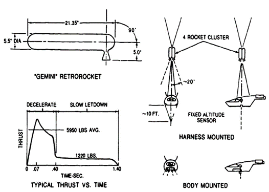
Two rocket installation concepts that have been tested, called harness mounted and body mounted, are shown in Figure 6-82. The harness-mounted installation was used in the Redhead/Roadrunner missile; it is self-centering with relation to the center of gravity of the vehicle-parachute system, and the rockets can be in the parachute compartment. However, a clear deployment path is necessary for moving the retrorockets from the compartment to the operational location; also, some riser heat protection may be required. The body-mounted installation was used on NASA JSC tests for developing a gliding retrorocket parachute landing system for the Gemini spacecraft. The development and full-scale flight tests are described in Reference 6.84, and some work done on the Apollo is described in Reference 6.85. The body-mounted installation is sensitive to center of gravity shifts; and on the Lunar excursion module, retrorockets stirred surface dust so that visibility was impaired.
Retrorockets, like most other impact attenuators, are designed for one energy level Increasing or decreasing the design rate of descent, stops the load above ground or produces a high ground shock. To cope with this problem, NASA developed for the Gemini landing system a two-step rocket. The high thrust level is decreased to a 0.9-g deceleration at the lowest energy level; this low-energy deceleration stops the vehicle slightly above the ground and gently lowers it for final landing.
Air Force investigations for using retrorockets for landing retardation of aircraft crew escape modules are discussed in Reference 6.86. The presence of potentially explosive components in the crew module was a design consideration.
The ratio of parachute air bag and parachute retrorocket weight to total vehicle weight was investigated for the B-1 crew module as shown in Figure 6-83. The optimum weight ratio for a parachute air bag system is obtained at the rate of descent of 25 to 30 ft/s. optimum weight for a parachute retrorocket system is in the range of 35 ft/s and above. This rate of descent may be too high for manned vehicles if the requirement exists for minimum aircrew injury at rocket malfunction.
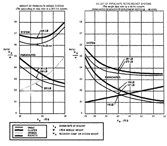
Several methods have been investigated and used for determining the exact starting altitude for the retrorockets. The Redhead/Roadrunner drone used an extendable mechanical feeler with a microswitch at the end of the feeler. A similar approach was used for the NASA-tested Gemini retrorocket concept and is used by the Soviet Union for its retrorocket impact attenuators for airdrop of heavy vehicle-platform systems. The Apollo Lunar Excursion Module (LEM) used a highly sensitive radar for firing the retrorockets for the moon landing. An optical altitude sensor for firing retrorockets at a precise altitude is described in Reference 6.87.
6.8.3.3 Skirt Jet Retrorocket System
Northrop, during the Apollo development, tested an unusual retrorocket concept called the "skirt jet," which was tailored to the Apollo command module. Figure 6-84 illustrates the concept. A tube filled with rocket fuel, and having a slotted nozzle, was placed around the skirt of the command module. Tests proved that firing the rocket tube less than 30 degrees inward increased the thrust close to the ground. Development and testing of this approach is discussed in Reference 6.88.
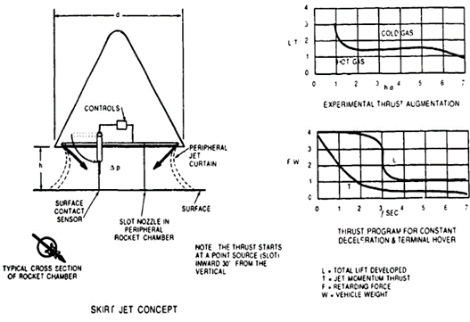
6.8.3.6 Special Impact Attenuators
Nose Cone Deformation: Several vehicles have used a crushable nose cone as an impact shock absorber. Use of a crushable nose cone requires that the vehicle or container descend in a nose-down attitude. The U.S. Army uses this concept on the airdroppable M4-A high-speed aerial delivery container. The container and the energy absorption characteristics are illustrated in Figure 6-85 taken from Reference 6.68.
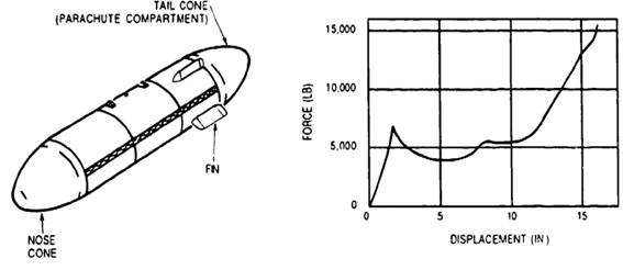
Nose Spike: Nose spikes have been used successfully for impact attenuation of mostly cylindrical containers descending in a vertical position. Figure 6-86 illustrates a typical nose spike arrangement, and Reference 6.89 describes the use of a nose spike as impact attenuator on the Lockheed X-7 supersonic ramjet test vehicle.

Nose spike impact attenuators are simple in design, reusable, require no maintenance, but have operational limitations. Nose spikes cannot be used in rocky terrain. A rate of descent of 35 ft/s is necessary to ensure sufficient ground penetration for the vehicle to remain upright. The ratio of vertical to horizontal velocity in high-wind landings should be 2.5 or better to prevent the vehicle from falling over and being damaged.
Water Landing: The Mercury, Gemini, Apollo, and the Space Shuttle solid rocket boosters (SRB) land on parachutes in water. Water is an excellent hydraulic shock absorber. However, all three manned spacecraft landed on the flat heat shield but under an angle to obtain a wedge-type water entry for limiting the impact deceleration to less than 6 g (References 5.10, 6.84, 6.90, 6.91, and 8.5 through 8.11).
The Space Shuttle SRB originally parachute-descended into the water at a rate of descent of 85 ft/s, based on model test results. However, this rate of descent had to be reduced to 75 ft/s to minimize damage to the rocket structure.
Airdropped mines and torpedoes use parachute retardation to limit water entry velocities to 200 ft/s or less to avoid structural damage and to obtain water entry angles that eliminate ricochet.
6.9 REFERENCE MATERIAL
6.1 T. P. Pawlikoski. "Drogue Mortar Simulation Development and Performance Evaluation." AIAA Paper, October 1986. (AIAA 86-2490.)
6.2 C. W. Peterson, et al. "Design and Performance of a Parachute for Supersonic and Subsonic Recovery of an 800-Lb Payload." AIAA Paper, October 1986. (AIAA 86-2435.)
6.3 J. L Charleville. "The F-111 Crew Module Development." AIAA Paper, September 1970. (AIAA 70-1210.)
6.4 B. A. Engstroem and W. C. Buhler. "Mid Air Retrieval System for the Air Launched Cruise Missile (Boeing AGM 68)." AIAA Paper, October 1981. (AIAA 81-1915,)
6.5 US. Air Force. G-11A Parachute Retardation System, by I. Svoboda, USAF, February 1961. (USAF Report FTC-TM-61-102.)
6.6 ____ Investigation of G-12D Parachute for Recovery of 8,000-lb Load, by C W. Marshall. USAF, July 1958. (USAF Report FTC-LR-59-110.)
6.7 U.S. Navy. Investigation of Low Bulk Personnel Parachute, 26-Ft Conical, by H.R. Moy. USN, El Centro, Calif., April 1953. (USNEC Report 7-53.)
6.8 U.S. Air Force. Development of a Final Stage Recovery System for a 10,000 Lb. Weight, by E. A. Gimalouski. USAF, December 1958. (USAF Report WADC-TR-59-109.)
6.9 G. A. Barnard. "Analysis of the Distribution of Load Among the Lines of an Inflating Cruciform Parachute." AIAA Paper. (AIAA 86-2441 CP.)
6.10 L. J. Long and Y. A. Stapenhill. "Development of a Large Cross Parachute with Deflation Pockets for a Water Landing Concept," AIAA paper, October 1986. (AIAA 86-2442 CP.)
6.11 A. J. Fallon, J. W. Watkins, and E. D. Vickery, "The Annular Parachute: An Approach to a Low Altitude Personnel Parachute," AIAA Paper, October 1986. (AIAA 86-2449.)
6.12 Specification MIL-P-5905A. "Parachute, Ribbed Guide Surface, General Specification for Construction of."
6.13 D. J. Kolega, W. R. Woodis, and J. D Reuter. "Vent Modification of Large Ribbon Parachutes to Enhance Cluster Performance." AIAA Paper, October 1986. (AIAA 86-2433.)
6.14 D W. Johnson, "All Radial Construction for Continuous Ribbon Parachutes." U.S. Patent No. 4-343-448.
6.15 General Dynamics. B-58 Escape Capsule Stabilization Parachute System Development, by T. H. Etherton, F. T. Burns, and L C. Norman, GD, Fort Worth, Tex., February 1962. (GD Report FZA-4-408.)
6.16 J. L. Charleville. "The F-111 Crew Escape Module." AIAA Paper, March 1970. (AIAA 70-1210.)
6.17 U.S. Air Force. Study and Exploratory Freeflight Investigation of Aerodynamic Decelerators Operating at High Altitudes and at High Mach Numbers, by W. E. Nickel and L. W. Simms. USAF, July 1964. (USAF Report FDL-TDR-64-35, Vol. 1.)
6.18 _____ Study of Parachute Performance and Design Parameters for High Dynamic Pressure Operation, by P. E. Pedersen. USAF, May 1964. (USAF Report FDL-TDR-64-66.)
6.19 L. W. Simms. "Concept, Aerodynamics, and Design Details of Hyper Flo Parachutes—A Summary." Paper presented at the University of Minnesota Short Course on Aerodynamic Deceleration, Minneapolis, Minn., July 1965.
6.20 National Aeronautics and Space Administration. An Investigation of the Initial Century Series Ringsail Parachutes, by L. C. Norman and K L Suit. NASA, August 1970. (NASA Report NASA-TND-5968.)
6.21 Irvin Industries, Inc. 20K Parachute System, Final Report. Il, August 1967. (IAC Report GIR 85-150.)
6.22 Naval Surface Warfare Center. Wind Tunnel Tests of a 20-Gore Disk-Gap-Band Parachute, by W. P. Ludtke. NSWC, May 1989. (NSWC TR 89-180.)
6.23 Royal Aircraft Establishment. A Geometric Basis for Taschengurt Design, by H.J. Waters. RAE, Farnborough, England, December 1953. (Mech Eng. Technical Note ME-162.)
6.24 _____.Tests in the 24-Ft Wind Tunnel for Increasing the Critical Opening Speed of a Parachute, by S. B. Jackson, C H. Trent, and T J. Nethrem. RAE, Farnborough, England. (Report AM-357).
6.25 J. E. Purvis. "Pocket Band Effect on Ringslot Parachutes." Paper presented at the University of Minnesota-CCG lecture on parachute systems technology. Munich-Oberpfaffenhofen, June 1987.
6.26 US Air Force. Investigation of the Relative Efficiency of Pilot Chutes, by R C. Cory. USAF, March 1956. (USAF Report WADC-TR.56-147.)
6.27 G, W. Stevens. "The Net-Skirt to a Parachute as a Device to Prevent Inversions." AIAA Paper October 1981. (AIM 81-1927.)
6.28 Royal Aircraft Establishment. The Net-Skirt Extension on Man-Carrying Type Parachutes, by G. W. Stevens. RAE, Farnborough. England. (Report ME.389.)
6.29 U. S. Army. Evaluation of T-IO Personnel Parachute With 3 3/5 Inch Mesh Net. USANDC, Natick, Mass., April 1975. (PIT. TECOM Project No. 8-EG060-010-003.)
6.30 U.S. Air Force. Deployment Bag. Parachutes, General Development, by R. W. Barnes. USAF, September 1949. (USAF Report MCREXE-672-23-L.)
6.31 K French. "A First Order theory for the Effect of Line Ties on Parachute Deployment." AIAA Paper, October 1974. (AIAA 74-0450.)
6.32 R. J. Speelman Ill. "Parachute Deployment Process Testing Technique,” AIAA Journal of Aircraft, Vol. 14, No. 4, pp. 401 and 402, 1977.
6.33 H. E. Widdows. "Parachute Deployment Control Assembly." U.S. Patent No. 3-145-956, August 1964.
6.34 D. T. Reynolds and W. M. Mullins. "Stress Analysis of Ribbon Parachutes." AIAA Paper, November 1975. (Al-AA 75-1372.)
6.35 W. L. Garrard. "Stress analysis in Parachute Canopies." Paper presented at the University of Minnesota-CCG lecture on parachute systems technology, Munich-Oberpfaffenhofen, June 1987.
6.36 W. L. Garrard, M. L Konicke. K. S. Wu, and K. K. Muramoto. "Measured and Calculated Stress in a Ribbon Parachute Canopy." AIAA Journal of Aircraft, Vol. 24, No. 2, pp. 65 to 72, February 1987.
6.37 W. D. Sundberg. "A New Solution Method for Steady-State Canopy Structural Loads." AIAA Paper. (AIAA 86-2489 CP)
6.38 K. G. Lindh. "Tension Impact Test on Nylon Webbing Structures." AIAA Paper, September 1970. (AIAA 70-1182.)
6.39 J. W. Purvis "Improved Prediction of Parachute Line Sail During Line-First Deployment" AIAA Paper, April 1984. (AIAA 84-0786.)
6.40 R. W. Rodier. "Reefing the Space Shuttle SRB.DSS Drogue Parachute." AIAA Paper, March 1979. (AIAA 79-0434.)
6.41 R. D. Moog, J. D. Sheppart, and D. A. Kross. "Space Shuttle Solid Rocket Booster Decelerator Subsystem Drop Test Results." AIAA Paper, March 1979. (AIAA 79-0463.)
6.42 D. W Johnson. "Status Report of a New Recovery Parachute System for the F-111 Aircraft Crew Escape System." AIAA Paper. (AIAA 86-2437 CP.)
6.43 Northrop Ventura. Reliability Trade-Off Analysis of Two-Stage Reefing System for Apollo Main Parachutes, by A. E. Johnson. NV, September 1967. (NV Report NVR-6055.)
6.44 National Aeronautics and Space Administration. Aerodynamic and Deployment Characteristics of Multi-Stage Canopy and Suspension Line Reefing System for a Twin-Keel All-Flexible Parawing, by H. L. Morgan and A. D. McHatton, NASA, July 1971. (NASA Report NASA-TN-D-6306.)
6.45 ______. Free Flight Investigation of Large All-Flexible Parawings and Performance Comparison With Small Parawings-Final Report, by J. H. Moller, E. M. Linhart, W. M. Gran, and L. T. Parson. NASA, March 1970. (NASA Report NASA-CR-66918.)
6.46 E. D. Vickery, M. L. Eldredge, C. R. Vernet, and W. G. Jolly. "Development of a System of Six Clustered 137-Ft. Diameter Parachutes for Recovery of a 60,000 Lb Load." AIAA Paper, October 1986. (AIAA 86-2445.)
6.47 D. W Johnson. "Apparatus for Simultaneously Disreefing a Centrally Reefed Clustered Parachute System." U.S. Patent No. 4-752-050, June 1988.
6.48 S. J. Barlog. "Practical Aspects of Reefing Cutter Design." AIAA Paper, March 1979. (AIAA 79-0418.)
6.49 Sandia National Laboratories. Development of an Electronic Time Delay Reefing Line Cutter for Parachutes, by W B. Pepper, G. H. Bradley, and W. C. Jacoby. SNL, December 1973. (SNL Report SLA-73-0989.)
6.50 _____. Development of the MC-3133 Reefing Line Cutter, by J. R. Craig. SNL, September 1977. (SNL Report SAND77-0955.)
6.51 Northrop Ventura. Apollo Main Cluster Reefing, by D. W. Dunn, S. J. Mel, and W. M. Gran. NV, May 1964. (NV Report NVR-3538.)
6.52 DuPont de Nemours & Co. Properties of DuPont Industrial Filament Yarns. DuPont de Nemours & Co., Textile Fiber Department, Technical Service Section, Wilmington, Del. 19898, April 1982. (DuPont Bulletin X-267.)
6.53 Naval Weapons Center. Evaluation of Lightweight Fabric Woven from 55 and 75 Denier Kevlar Yarn, by R. W. Hunter. NWC, China Lake, Calif., 1 February 1984. (NWC TM 5170).
6.54 C. W Peterson, W R. Pepper, D. W. Johnson, and I. T. Holt. "Kevlar Parachute Design and Performance." AIAA Paper, April 1984. (AIAA 84-0810 CP.)
6.55 J. F. McNelia. "Relative Volumetric Efficiency of Kevlar vs. Nylon Parachute Designs." Paper presented at the Parachute Manufacturing Seminar, Piedmont Community College, Roxboro, N. C. 27573, March 1988.
6.56 U.S. Air Force. Materials and Design Criteria for Kevlar Ribbon Parachutes, by W. R. Pinnell. USAF, April 1982. (USAF Report AFWAL-TR-81-3138.)
6.57 S. Beare. "New Lightweight Parachute Fabrics of Kevlar Aramid Fiber," AIAA Paper, April 1989. (AIAA 89-0911.)
6.58 U.S. Air Force. Development of Kevlar 29 Decelerator Systems Material, by N. J. Abbott and R. J. Coskren. USAF, November 1978. (USAF Report AFFDL-TR-78-201.)
6.59 Naval Weapons Center. Evaluation of Kevlar Materials, FY 83 to FY 85, by R. I. Tubis. NWC, China Lake, Calif., August 1985. (NWC TM-5604.)
6.60 U.S. Air Force. Kevlar Properties Investigation, High-Speed Abrasion Resistance, by S. L. Goodwin and N. J. Abbott. USAF, February 1980. (AFWAL-TR-80-300)
6.61 Naval Weapons Center. Kevlar Stitching Patterns, by R. I. Tubis. NWC, China Lake, Calif., September 1986. (NWC TP 6761.)
6.62 K. E. French. "A New Correlation of Parachute Weight Data."AIAA Journal of Spacecraft and Rockets, Vol. 8, No. 1, January 1971, pp. 71 and 72.
6.63 U.S. Air Force. Study of Pressure Packing Techniques for Parachutes, by W. J. Bridwell. USAF, September 1961. (USAF Report ASD-TR-61-426.)
6.64 National Aeronautics and Space Administration. Analytical Investigation of an Inflatable Landing System Omnidirectional and Multiple Impact Capability, by J. R. McGehee. NASA, May 1969. (NASA Report NASA-TN-D-5236)
6.65 _____ . A Mathematical Procedure for Predicting the Touchdown Dynamics of a Soft-Landing Vehicle, by G. A. Zupp. NASA, February 1971. (NASA Report NASA-TN-D-7045.)
6.66 U.S. Navy. Application of Analog/Hybrid and Hybrid Computers to the Study of Shock Mitigation Systems, by C. L. Patterson. NSRD, November 1970. (NSRD4A-6-28/70.)
6.67 U.S. Army. Design of Cushioning Systems for Air Drop, by M. P. Gionfriddo. USANDC, Natick, Mass., February 1967. (USANDC Report 67-59-AD.)
6.68 U.S. Army Material Command. "Design for Air Transport and Air Drop of Material," Engineering Design Handbook. USAMC, December 1967. (Pamphlet No. AMCP 706-130.)
6.69 University of Texas. Design of Cushioning Systems for Air Delivery of Army Equipment, by D. C. Ellus. UT, Austin, Tex, August 1961.
6.70 U.S. Army NLABS. Variations in the Crushing Strength of Paper Honeycomb, by E. P. Ripperger. USANLABS, December 1969. (USANLABS-TR-70-57-AD)
6.71 University of Texas. Cushioning for Air Drop, Parts I to VIII, by J. W. Turnbow, et al. UT, Austin, Tex., 1955 to 1958. (Publications of UT, Structural Mechanics Research Laboratory.)
6.72 U.S. Air Force. Development of a Paperboard Honeycomb Decelerator for Use With Large Platforms in Aerial Delivery Systems, by H. W. Bixby. USAF. (USAF Report WADC.TR.59-776.)
6.73 National Aeronautics and Space Administration. The Design and Development of Radio-Frequency Transparent Omnidirectional Energy-Absorbing Element Systems, by R. H. Smith. NASA, January 1967. (NASA Report NASA-CR-66301.)
6.74 S.R. Mehaffie. "Foam Impact Attenuation System." AIAA Paper. (AIAA 79-0416.)
6.75 Northrop Ventura. Impact Attenuation Systems, by M. Neustadt. NV, December 1963. (NV Report NVR-2900.)
6.76. K. Idomir. "TM-76 Mace Landing Mat Design," Aero/Space Engineering, Vol. 19, February 1960, pp. 28 to 34.
6.77 U.S. Air Force. Experimental Investigation of the Ground Impact Characteristics of a Full-Scale Aircraft Emergency Escape Capsule System (F-111), by R. L Peterson and E. O. Roberts. USAF, July 1972. (USAF Report AFFDL-TR-72-34.)
6.78 _____. Analysis of B-1 Crew Escape Module Impact Attenuation Test results, by E. O. Roberts. USAF, February 1974. (USAF Report AFFDL.TM.74-30-FER.)
6.79 C. T. Turner and L. A, Girard, Jr. "Air Bag Impact Attenuation System for the AQM-34V Remote Piloted Vehicle." AIAA Paper, October 1981. (AIAA 81-1917.)
6.80 D. Webb and L Palm. "Development of a Nylon-Kevlar Recovery System for the CL-289 (USD-502) Surveillance Drone." AIAA Paper, October 1981. (AIAA 81-1952.)
6.81 North American Aviation. Redhead/Roadrunner Target/Missile System, Final Report. NAA, February 1966. (NAA Report 64H-460 (AD 482 818).)
6.82 U. S. Army NLABS, Parachute Retrorocket Airdrop System, Final Engineering Report, by J. L. Michael, A. L. Oates, and A. L. Martinez. USANLABS, July 1972.
(USANLABS-TR-72-16 (AD 736 .361).)
6.83 U. S. Army NLABS. Advanced Development of a Parachute Retrorocket Airdrop System, by G. Chokoian. USANLABS, May 1973. (USANLABS-TR-73-59.)
6.84 National Aeronautics and Space Administration. Gemini Land Landing System Development Program, Vol. I and Il, by L. C. Norman. NASA, March 1967. (NASA Report NASA-TN-D-3869.)
6.85 _____. Attenuation of Land Landing for Manned Spacecraft, by J. E. McCullough, F. A. Stafford, and F. A. Benson. NASA, April 1964. (NASA Report NASA-CR-53291.)
6.86 U.S. Air Force. Design Analysis for a Parachute/Retrorocket Landing System for an Aircraft Crew Escape Module, by C. A. Babish. USAF, February 1973. (USAF Report AFFD/FER.)
6.87 _____. An Active Optical Ground Sensor for a Parachute Retrorocket Airdrop System, by R. Ulrich and A. J. D'Onofrio. USAF, February 1973. (USAF Report HDL-TM-73-2 (AD 911 216L).)
6.88 E. G. Ewing and G. Frank. "The 'Skirt Jet' Impact Attenuation System," Proceedings of the AIAA Aerodynamic Deceleration Systems Conference. Houston, Tex., September1966.
6.89 U.S. Air Force. X-7A Supersonic Ramjet Test Vehicle Parachute Recovery System. USAF, June 1955. (USAF Report WADC-55-162.)
6.90 Northrop Ventura. Project Mercury, Landing Parachute Development and Qualification, by W. C. Buhler. NV, October 1961. (Northrop-Radioplane Report No. 2312.)
6.91 National Aeronautics and Space Administration. Project Gemini, A Technical Summary, by P. W Malik and G. A. Souris. (NASA Report NASA-CR.1106.)
6.92 E. Hennings. "Substitution of Reefing Loops for Reefing Rings in Pressure Packing," AIAA Paper, May 2007. (AIAA 2007-2536)
6.93 B. Anderson, J. Daum, S. Tawdros. "Textile Material Lessons Learned During the Design and Qualification of the NASA Orion Capsule Parachute Assembly System," AIAA Paper. June 2019. (AIAA 2019-2894)


