Parachute Aerodynamics
CHAPTER 4: AERODYNAMICS AS RELATED TO PARACHUTES
4.1 PROPERTIES OF THE ATMOSPHERE
All forces acting on parachutes and all movements of parachutes are affected by the atmosphere, or air, surrounding the Earth. The air at the Earth's surface is approximately 78% nitrogen; 21% oxygen; and 1% a mixture of gases such as argon, neon, helium, water vapor, and carbon dioxide. This chemical composition remains relatively constant to an altitude of about 160,000 feet (50 kilometers). The following air qualities are of major significance in the dynamics of bodies moving in the atmosphere:
| Air quality | Symbol | Dimension |
|---|---|---|
| Specific weight of air | w | lb/ft3, kg/m3 |
| Static pressure | p | atm, lb/ft2, Pa, bar, torr |
| Temperature | T | oF, oC |
| Mass density | slugs/ft3, kg s2/m4 | |
| Gravity | g | ft/s2, m/s2 |
| Speed of sound | Cs | ft/s, m/s |
All of these qualities are altitude-dependent and may vary slightly on the Earth's surface with geographic latitude because of variations of the Earth's radius caused by the centrifugal forces of the rotation of the Earth. All standard data used herein refer to a latitude of 45 degrees. Sea level is defined as mean sea level (MSL). To compare performance data on an equal basis, the United States Bureau of Standards has defined standard day conditions as follows:
- Temperature = 15 degrees Celsius (oC) or 59 degrees Fahrenheit (oF)
- Pressure = 760 millimeters (mm) of mercury (Hg) or 29.9213 inches (in.) Hg
4.1.1 Specific Weight of Air
For standard day conditions of 59 oF temperature and a pressure of 29.9213 in. Hg, the specific weight of air, w, is 0.07648 lb/ft3 or 1.2250 kg/m3. The specific weight of air changes with pressure, temperature, and humidity. Further data can be found in References 3.4 and 4.1, and in technical handbooks.
4.1.2 Static Pressure
Static pressure depends on geographic latitude, weather conditions, and altitude. The static pressure at any altitude results from the weight of the air above that altitude. For MSL and standard day conditions, the pressure, po, is 29.9213 in. Hg = 760 mm Hg = 1.0 atmosphere (atm). For conversion to Pascal, torr, or bar, see the conversion tables in section 3.2.
4.1.3 Temperature
Temperatures are defined in the English and metric systems in the so-called absolute and engineering scales. The absolute temperature minimum at 0 degrees, pressure is 0 oK = -273.16 oC, and 0 oR = -459.69 oF. This is also written
- Degrees Kelvin = degrees Celsius + 273.16
- Degrees Rankine = degrees Fahrenheit + 459.69
The freezing point of water is 32 oF or 0 oC. The boiling point of water is 212 oF or 100 oC.
4.1.4 Mass Density of Air
Mass density defines the amount of mass contained in a unit volume of air. The mass density, , of air is of special importance in aerodynamic calculations.
Frequently the density ratio, Failed to parse (Conversion error. Server ("https://wikimedia.org/api/rest_") reported: "Cannot get mml. Server problem."): {\displaystyle \sigma } , is used
The factor, , determines the increase in parachute rate of descent with altitude. The density at 40,000 feet is ¼ of the MSL density, and the density at 100,000 feet is 1/75 of the MSL density. Therefore, the parachute rate of descent is about twice as high at 40,000 feet and about nine times as high at 100,000 feet. MSL density is 0.00237689 slugs/ft3, or 0.1249 kg s2/m4.
4.1.5 Gravity
Any mass attracts another mass with a force called gravity. If the Earth were surrounded by a vacuum, a body suspended above the Earth and released would fall toward the center of the Earth with increasing velocity caused by the acceleration of gravity, g. In reality, the falling body is decelerated by its air drag until the air drag, D, equals the weight of the body, W, and an equilibrium velocity is reached; for parachutes, this is called the steady-state rate of descent.
The acceleration of gravity, g, at sea level is
g = 32.174 or 9.80665 .
The value g = 9.08665 m/s is standardized internationally but is accurate only for a latitude of 45 degrees.
With increasing altitude above the Earth's surface, the acceleration of gravity decreases in accordance with the equation
where
- g = acceleration of gravity at any altitude, ft/s2
- go = acceleration of gravity at sea level, ft/s2
- r = average Earth radius = 2.08556 x 107 ft
- h = altitude above sea level, ft
For other planets and heavenly bodies, the acceleration of gravity varies with the mass of the body. For example, the acceleration of gravity on Mars is about 1/3 of the acceleration of gravity on Earth. For more details on planets and heavenly bodies, see page XII of Reference 2.1.
4.1.6 Kinematic Viscosity
The coefficient of viscosity, , defines the shearing stresses in a gas or liquid and is sometimes called the resistance to continuous deformation. In aerodynamics, the coefficient of viscosity is combined with the mass density to form the kinematic viscosity, , where
The kinematic viscosity, , is altitude dependent and is used to calculate the Reynolds number, Re.
4.1.7 Reynolds Number
The Reynolds number, Re, defines the relationship of mass forces to viscous friction forces in liquids and gases. It is calculated as
Reynolds number is an important criterion in subsonic, noncompressible flow, and allows comparison of model tests with full-scale flight tests. A Reynolds number effect on parachutes working in separated, turbulent flow has not yet been established, as shown in section 5.2. The following chart shows the Reynolds numbers for various air vehicles.
| Subject | Insect | Glider | DC-3 | B-747 | Drogue
Chute |
Main
Parachute |
WTT
Model |
|---|---|---|---|---|---|---|---|
| Re | 6 • 103 | 2.5 • 106 | 24 • 106 | 100 • 106 | 50 • 106 | 20 • 106 | 2 • 106 |
4.1.8 Mach Number
Mach number is an important parameter of supersonic flight; it states how much faster than the speed of sound the air vehicle travels.
The speed of sound is the velocity at which a pressure disturbance, such as the sound of the human voice, travels in any medium. The speed of sound varies considerably in different gases, liquids, and metals.
| Speed of sound in air in MSL | Cs = 1116.46 ft/s = 340.38 m/s |
| Speed of sound in water | Cs = 4749 ft/s = 1461.21 m/s |
| Speed of sound in iron | Cs = 16,410 ft/s = 5710.7 m/s |
The speed of sound depends on temperature and the chemical composition of the medium, A widely used equation for speed of sound in air is
where
- = speed of sound in dry air, ft/s
- = ratio of specific heat, equal to 1.4 for dry air, dimensionless
- = temperature in Fahrenheit absolute, equal to 459.67 + oF
The speed of sound changes with altitude, as temperature (see Figure 3-1). The drag of streamlined bodies such as missiles, airfoils, and airplanes increase considerably as their velocities approach Mach 1. Depending on the configuration of the body, supersonic compressibility effects may occur in the 0.75 to 0.85 Mach range, causing local supersonic flow, shock waves, flow separation, and concomitant increases in drag and changes in stability.
Parachutes that operate in separated flow over the entire velocity range do not show the typical drag increase when operating close to or beyond Mach 1. Supersonic parachute behavior is discussed in detail in section 5.8.
4.2 CONTINUITY LAW AND BERNOULLI EQUATION
4.2.1 Continuity L.aw
Air is thought to flow in layers called streamlines. Figure 4-1 shows streamlines as layers of air without air transfer between individual layers. ne air is shown as being incompressible, a valid assumption for subsonic flow.
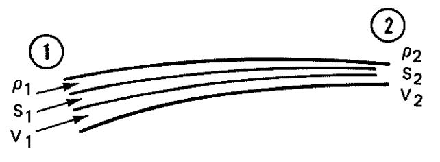
If exchange of air does not occur across the streamline boundaries, the amount of air entering the streamline at point 1 must also exit at point 2, as shown in Figure 4-1. Because the cross section at point 2 is smaller than the cross section at point 1, the air must exit at a higher velocity. The following equation defines this condition:
where
= cross section of the streamline
= velocity in the streamline
= density of the air flowing in the streamline
This equation, which governs the flow in and around a body in gases and liquids, is important in aerodynamics and is called the Continuity Law. For incompressible subsonic flow, it can be simplified to
Whenever the cross section narrows, the velocity increases; when the cross section widens, the velocity decreases.
4.2.2 Bernoulli Equation
Figure 4-2 illustrates a streamline with the cross section, S, the velocity, v, and the pressure, p. If the air is incompressible, the downstream is v + Failed to parse (Conversion error. Server ("https://wikimedia.org/api/rest_") reported: "Cannot get mml. Server problem."): {\displaystyle \Delta } v. and the pressure is p + Failed to parse (Conversion error. Server ("https://wikimedia.org/api/rest_") reported: "Cannot get mml. Server problem."): {\displaystyle \Delta } P. If the air is inviscid, the inertia forces caused by the acceleration of air from v to v + Failed to parse (Conversion error. Server ("https://wikimedia.org/api/rest_") reported: "Cannot get mml. Server problem."): {\displaystyle \Delta } v must be balanced by differential pressure forces.
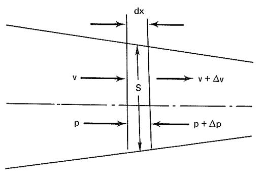
The following equation can be written
Simplified, the above equation yields
and
The above equation allows the following consideration: If p is pressure, then and must also be pressure. The equation includes a velocity and is referred to as the dynamic pressure, or sometimes as velocity or impact pressure.
Pressure, Failed to parse (Conversion error. Server ("https://wikimedia.org/api/rest_") reported: "Cannot get mml. Server problem."): {\displaystyle p} , is defined as static pressure; as dynamic pressure; and the sum of both, , as the total pressure or
and
where is the total pressure of the system, lb/ft2.
Dynamic pressure, , is a frequently used quantity in aerodynamics:
where
- = dynamic pressure, lb/ft2
- = air density, slugs/ft3
- = velocity at a point of undisturbed flow, ft/s
The following formulas are used for calculating the sea-level dynamic pressure if the velocity is given in ft/s, knots, mph, or km/h, respectively:
4.3 NEWTON'S THREE LAWS OF MOTION
Engineering mechanics are governed by the following three laws of Isaac Newton:
1. A body remains at rest or in an unaccelerated state of motion unless acted upon.
2. A force acting upon a body will produce an acceleration in the direction of the force.
3. An action in one direction will produce an equal reaction in the opposite direction.
The first law is self-explanatory. The second law may be expressed by the equation
where
= force in pounds acting on the mass, lb
Failed to parse (Conversion error. Server ("https://wikimedia.org/api/rest_") reported: "Cannot get mml. Server problem."): {\displaystyle m} = mass of body that the force is acting upon, slugs
= acceleration in ft/s2 resulting from the force, F
The mass, m, of a body is obtained by
where
= weight of the body, lb
= acceleration of gravity, ft/s2
The mass, therefore, has the dimension of
This unit of mass is the slug.
The equation of Newton's second law can now be written
The factor a/g is frequently called the load factor, G, and tells how much larger a force is than a force equivalent to the weight of the body. It is customary in parachute work to state that the maximum parachute force allowed is G • W or (a/g) • W. It is appropriate to write
Maximum allowable parachute force,
Figure 4-3 illustrates Newton's third law, explaining the principle of the rocket that can produce thrust in a perfect vacuum.
A mass, m, ejected from a rocket at the velocity, v, per unit time, t, will produce a force, F, which in turn will create a reaction force, R, of equal magnitude but acting in the opposite direction.

4.4 FORCES ACTING ON A BODY MOVING THROUGH AIR
4.4.1 Symmetrical Body
A body moving through air experiences forces caused by air pressure acting on the body. The same forces if the body moves through air, such as a descending parachute, or if the body is fixed and the air moves against the body, such as a parachute or an airfoil in a wind tunnel (Figure 4-4).
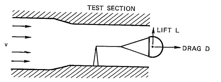
A stable parachute in a wind tunnel experiences only the force called "drag" in the direction of the airflow. drag force, D, is calculated to
where
= drag, lb
= dynamic pressure, lb/ft2
= total surface area of the parachute canopy, ft2
= coefficient of drag, dimensionless
The dynamic pressure, q, can be calculated from section 4.2.2. The surface area of the canopy, S, is selected as a reference area. The drag coefficient, CD, is a form factor that indicates the drag characteristic of a specific shape. Most aerodynamic bodies are designed for low drag or a low drag coefficient. Parachutes, generally, are designed for high drag; therefore, a high drag coefficient is desirable. this difference in drag is demonstrated by the two bodies shown in Figure 4-5.

Both bodies have the same cross section perpendicular to the airflow. The cylindrical. streamlined body has a smooth airflow over its total body length, resulting in a drag coefficient. CD, of 0.05 to 0.1, depending on slenderness ratio, surface roughness, and shape. The drag coefficient of all streamlined bodies is much affected by Reynolds number and Mach number. The open hemisphere, which is similar to a parachute canopy, has a drag coefficient, CD, of 1.3 to 1.4 for the same body cross section. The difference in drag is explained by the smooth airflow around the streamlined body and a separated, turbulent flow around the open hemisphere. The drag of bodies with separated flow, like parachute canopies, is little affected by Reynolds number.
4.4.2 Airflow Around an Asymmetrical Body (Airfoil)
Figure 4-6 shows an airfoil fixed at an angle of attack, . against the airflow in a wind tunnel. This airfoil creates a drag force, D, in the direction of the flow; a lift force L perpendicular to the direction of the flow; and a moment, M. around the attachment point of the airfoil. fie sign convention of moments and forces shown are positive. Lift and drag can be combined for the resultant force, R.
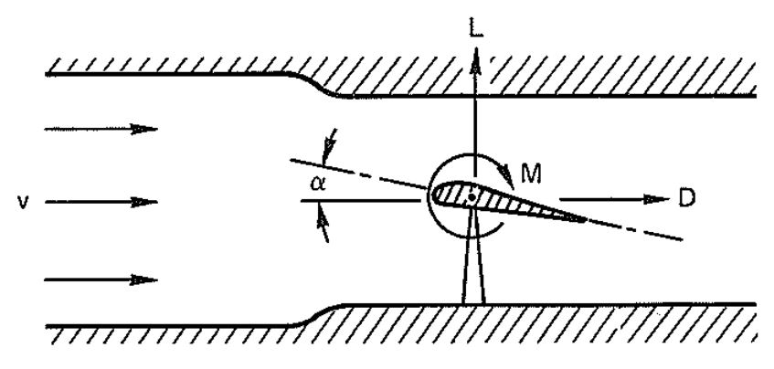
The lift, L is calculated
where
= measured lift, lb
= dynamic pressure, lb/ft2
= reference area, ft2
= lift coefficient, dimensionless
The moment is
where
Failed to parse (Conversion error. Server ("https://wikimedia.org/api/rest_") reported: "Cannot get mml. Server problem."): {\displaystyle M} = measured lift, lb
= dynamic pressure, lb/ft2
= reference area, ft2
= moment coefficient, dimensionless
= average chord width of the wing, ft
The reference area, S, is defined by agreement. For streamlined bodies, the maximum body cross section is used. Airfoils use the planform of the wing, and parachutes use the canopy surface area. The selection of the wing planform and the parachute surface area as references was made for practical reasons. The wing planform for a specific wing is fixed, whereas the cross section of the wing in the direction of the flow changes with the angle of attack. Similarly, the surface area of the parachute canopy is fixed; however, the frontal projected area of the inflated parachute canopy changes with airspeed, porosity, line length, and type of parachute.
Forces and moments acting on an airfoil or a parachute canopy may be presented in several ways. The two most frequently used methods, as shown in Figure 4-7, are with forces oriented to the axis of flight and with forces oriented to the axis of the airfoil.
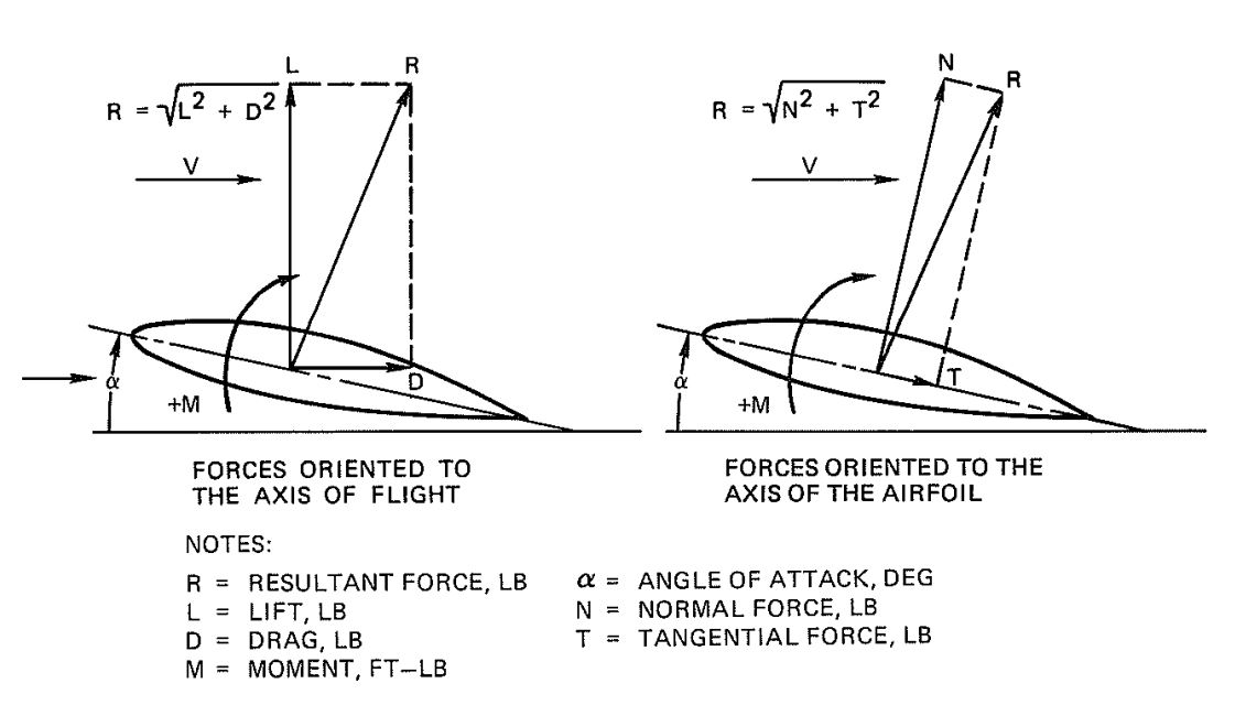
The tangential force, and the normal force, N, are calculated
and
where
CT = tangential force coefficient, dimensionless
CN = normal force coefficient, dimensionless
The resultant force, R, and the moment, M, in both presentations have the same direction and the same magnitude. The airflow fixed system is preferred for aerodynamic performance calculations, and the airfoil fixed system for wing stress calculations. me aerodynamic coefficients CL, CD, CT, CN, and Cm can easily be determined in wind tunnel measurements.
Figure 4-8 shows the relationship of both force systems on a parachute. By definition, a negative moment is stabilizing, as illustrated in Figure 4-8. It is interesting to note that in Europe the stabilizing moment is defined as positive. Wind-tunnel installations frequently measure normal and tangential force instead of lift and drag. If α, T, and N are known, the drag D, can be calculated
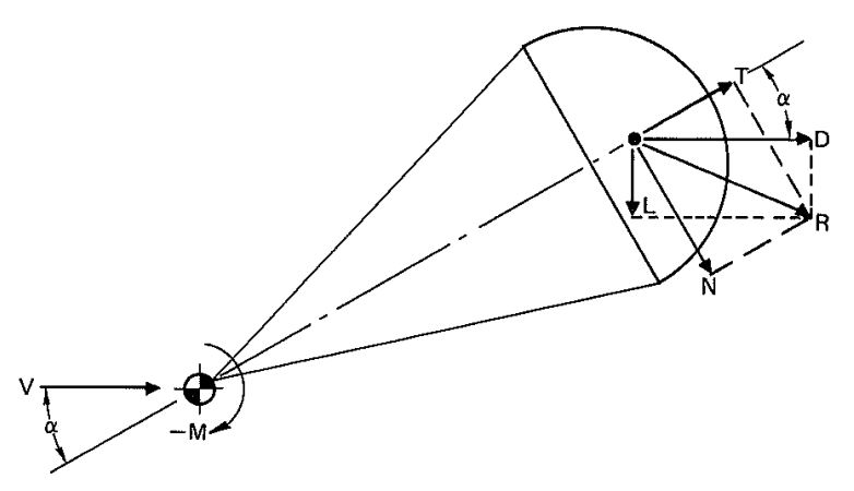
For a parachute with an angle of attack, , equal to zero, the drag force and the tangential force are synonymous.
Figure 4-9 shows the coefficients CT, CD, and Cm versus angle of attack for stable and unstable parachutes.
The coefficient presentation shows two interesting facts. The slope of the moment coefficient curve, dCm/dα, for the unstable parachute is positive between -25 degrees and + 25 degrees; this is, by definition, destabilizing. This parachute will oscillate approximately ± 25 degrees. The slope of the moment, dCm/dα, for the stable parachute is negative over the total angle of attack; this is, by definition, stabilizing. The steeper the negative dCm/dα slope, the greater is the stabilizing tendency of the parachute, and the better is its damping capability against unstabilizing forces such as sudden gusts of wind.
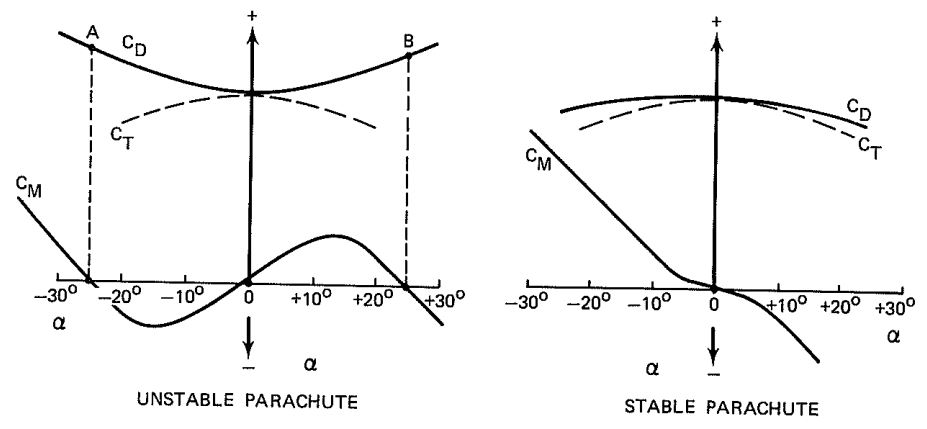
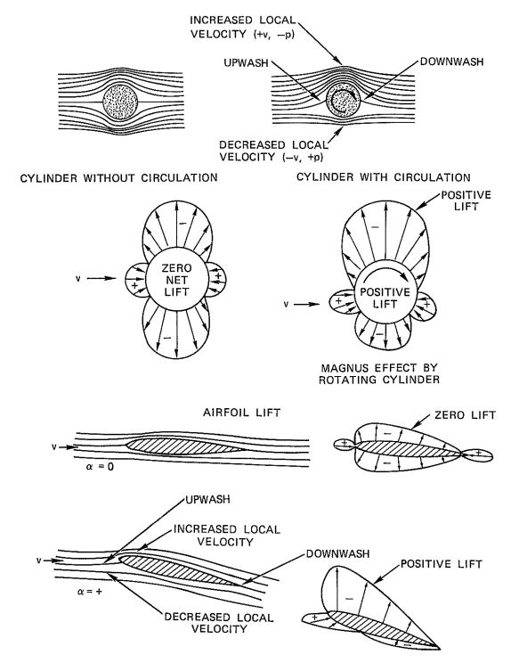
Figure 4-10, from Reference 4.1, demonstrates the effect of airflow around a cylinder and an airfoil. The circulation around a rotating cylinder creates lift caused by the increase in velocity on one side of the cylinder and a decrease on the opposite side. This is called the Magnus effect.
4.5 EQUILIBRIUM OF FORCES IN STUDY DESCENT OR FLIGHT
4.5.1 Parachute in Steady Descent
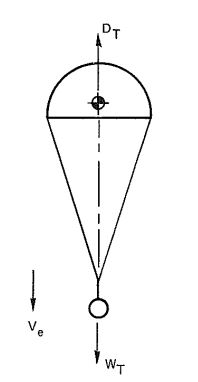
A stable parachute in unaccelerated descent has an equilibrium between the total drag of the parachute and the load, , and the weight of the load and the parachute assembly, (Figure 4-11). For steady descent
where
= total drag, lb
= drag of parachute, lb
= drag of load, lb
= total weight, lb
= weight of parachute, lb
= weight of load, lb
In most cases, the drag of the load can be neglected in relation to the large drag of the parachute, With drag, Failed to parse (Conversion error. Server ("https://wikimedia.org/api/rest_") reported: "Cannot get mml. Server problem."): {\displaystyle D=(C_{D}S)_{p}\cdot \rho /2\cdot v^{2}} . and and solving for v, the important equation for rate of descent, v, is obtained.
Rate of descent,
or in parachute terminology for rate of descent at sea level
Failed to parse (Conversion error. Server ("https://wikimedia.org/api/rest_") reported: "Cannot get mml. Server problem."): {\displaystyle v_{e_{o}}={\sqrt {\frac {2W_{T}}{S_{o}\cdot C_{D_{o}}\cdot \rho _{o}}}}}
and rate of descent at any altitude
For , see column 4 in Table 3-3.
In the equation for rate of descent, ,
= weight of load and parachute assembly, lb
= canopy surface area,
= parachute drag coefficient related to So
Failed to parse (SVG (MathML can be enabled via browser plugin): Invalid response ("Math extension cannot connect to Restbase.") from server "https://wikimedia.org/api/rest_v1/":): {\displaystyle \rho} = air density at a specific altitude in Failed to parse (SVG (MathML can be enabled via browser plugin): Invalid response ("Math extension cannot connect to Restbase.") from server "https://wikimedia.org/api/rest_v1/":): {\displaystyle slug/ft^3} , as shown in Table 3-3
During descent from altitude, the parachute system is constantly decelerated because of the increasing air density. This can be ignored for slowly descending main parachutes. However, for drogue chute systems that descend at 200 ft/s or faster, the constant deceleration may result in velocities 3 to 5% higher than the steady rate of descent.
4.5.2 Gliding Parachutes
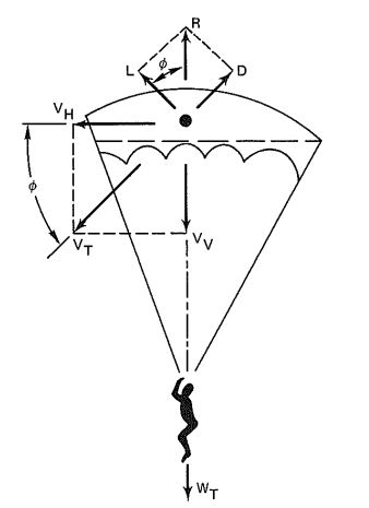
Figure 4-12 shows the balance of forces on a gliding parachute. The total weight of the system, Failed to parse (SVG (MathML can be enabled via browser plugin): Invalid response ("Math extension cannot connect to Restbase.") from server "https://wikimedia.org/api/rest_v1/":): {\displaystyle W_T} . must be balanced by the resultant force. R. However, a lifting force is required for glide. To satisfy the force balance
Failed to parse (SVG (MathML can be enabled via browser plugin): Invalid response ("Math extension cannot connect to Restbase.") from server "https://wikimedia.org/api/rest_v1/":): {\displaystyle R=W_T}
Failed to parse (SVG (MathML can be enabled via browser plugin): Invalid response ("Math extension cannot connect to Restbase.") from server "https://wikimedia.org/api/rest_v1/":): {\displaystyle R=\sqrt{L^2+D^2}}
Failed to parse (SVG (MathML can be enabled via browser plugin): Invalid response ("Math extension cannot connect to Restbase.") from server "https://wikimedia.org/api/rest_v1/":): {\displaystyle R=C_R\cdot S \cdot \rho /2 \cdot v^2_T }
Failed to parse (SVG (MathML can be enabled via browser plugin): Invalid response ("Math extension cannot connect to Restbase.") from server "https://wikimedia.org/api/rest_v1/":): {\displaystyle C_R=\sqrt{C_L^2+C_D^2}}
Trajectory velocity, Failed to parse (SVG (MathML can be enabled via browser plugin): Invalid response ("Math extension cannot connect to Restbase.") from server "https://wikimedia.org/api/rest_v1/":): {\displaystyle v_T} , is calculated
Failed to parse (SVG (MathML can be enabled via browser plugin): Invalid response ("Math extension cannot connect to Restbase.") from server "https://wikimedia.org/api/rest_v1/":): {\displaystyle v_T=\sqrt{\frac{2W}{S \cdot \rho}\cdot \frac{1}{\sqrt{C_L^2+C_D^2}}}}
or
Failed to parse (SVG (MathML can be enabled via browser plugin): Invalid response ("Math extension cannot connect to Restbase.") from server "https://wikimedia.org/api/rest_v1/":): {\displaystyle v_T=\sqrt{\frac{2W}{S \cdot \rho}\cdot \frac{1}{C_R}}}
Horizontal velocity is calculated
Failed to parse (SVG (MathML can be enabled via browser plugin): Invalid response ("Math extension cannot connect to Restbase.") from server "https://wikimedia.org/api/rest_v1/":): {\displaystyle v_H=v_T \cdot cos\phi } , and vertical velocity, Failed to parse (SVG (MathML can be enabled via browser plugin): Invalid response ("Math extension cannot connect to Restbase.") from server "https://wikimedia.org/api/rest_v1/":): {\displaystyle v_v=v_T \cdot sin \phi}
The glide ratio is obtained from
Failed to parse (SVG (MathML can be enabled via browser plugin): Invalid response ("Math extension cannot connect to Restbase.") from server "https://wikimedia.org/api/rest_v1/":): {\displaystyle \frac{L}{D}=\frac{v_H}{v_v}=\frac{C_L}{C_D}}
Analysis of Figure 4-12 indicates that the larger the ratio of lift to drag, the better the glide ratio, L/D. A high resultant coefficient, Failed to parse (SVG (MathML can be enabled via browser plugin): Invalid response ("Math extension cannot connect to Restbase.") from server "https://wikimedia.org/api/rest_v1/":): {\displaystyle C_R} , results in a low glide or trajectory Failed to parse (SVG (MathML can be enabled via browser plugin): Invalid response ("Math extension cannot connect to Restbase.") from server "https://wikimedia.org/api/rest_v1/":): {\displaystyle v_T} , desirable for landing. A small Failed to parse (SVG (MathML can be enabled via browser plugin): Invalid response ("Math extension cannot connect to Restbase.") from server "https://wikimedia.org/api/rest_v1/":): {\displaystyle C_R} results in a high glide velocity, Failed to parse (SVG (MathML can be enabled via browser plugin): Invalid response ("Math extension cannot connect to Restbase.") from server "https://wikimedia.org/api/rest_v1/":): {\displaystyle v_T} , which is desirable for flying toward a target, compensating for head winds, or covering a distance quickly. Generally, gliding parachutes follow the same aerodynamic rules as low-aspect-ratio wings.
4.5.3 Parasite Drag and Induced Drag
The drag acting on a lift-producing air vehicle, such as a gliding parachute or an aircraft, has two primary components: the parasite drag, Failed to parse (SVG (MathML can be enabled via browser plugin): Invalid response ("Math extension cannot connect to Restbase.") from server "https://wikimedia.org/api/rest_v1/":): {\displaystyle D_p} , and the induced drag. Failed to parse (SVG (MathML can be enabled via browser plugin): Invalid response ("Math extension cannot connect to Restbase.") from server "https://wikimedia.org/api/rest_v1/":): {\displaystyle D_i} .
Parasite drag is produced by the form drag from individual components such as the suspension lines, canopy, and the jumper of a gliding parachute, and the fuselage, tail section, and control surfaces of an airplane. Large surfaces produce surface friction drag as part of the parasite drag.
Induced drag is caused by the lifting action of the parachute canopy or the aircraft wing. Section 4.7 includes books with detailed discussions of induced drag.
Total drag, Failed to parse (SVG (MathML can be enabled via browser plugin): Invalid response ("Math extension cannot connect to Restbase.") from server "https://wikimedia.org/api/rest_v1/":): {\displaystyle D_T}
, can be defined as
Failed to parse (SVG (MathML can be enabled via browser plugin): Invalid response ("Math extension cannot connect to Restbase.") from server "https://wikimedia.org/api/rest_v1/":): {\displaystyle D_T=D_p+D_i}
or, in the coefficient form
Failed to parse (SVG (MathML can be enabled via browser plugin): Invalid response ("Math extension cannot connect to Restbase.") from server "https://wikimedia.org/api/rest_v1/":): {\displaystyle C_{D_T}=C_{D_p}=C_{D_i}}
The parasite drag, Failed to parse (SVG (MathML can be enabled via browser plugin): Invalid response ("Math extension cannot connect to Restbase.") from server "https://wikimedia.org/api/rest_v1/":): {\displaystyle D_p} , and the coefficient, Failed to parse (SVG (MathML can be enabled via browser plugin): Invalid response ("Math extension cannot connect to Restbase.") from server "https://wikimedia.org/api/rest_v1/":): {\displaystyle C_{D_p}} , can be determined in wind-tunnel tests or calculated as the sum of the individual component drags.
The induced drag coefficient, Failed to parse (SVG (MathML can be enabled via browser plugin): Invalid response ("Math extension cannot connect to Restbase.") from server "https://wikimedia.org/api/rest_v1/":): {\displaystyle C_{D_i}} , of a gliding parachute canopy or a wing profile can be calculated
Failed to parse (SVG (MathML can be enabled via browser plugin): Invalid response ("Math extension cannot connect to Restbase.") from server "https://wikimedia.org/api/rest_v1/":): {\displaystyle C_{D_i}=\frac{C_L^2 \cdot S}{\pi \cdot b^2}}
where
Failed to parse (SVG (MathML can be enabled via browser plugin): Invalid response ("Math extension cannot connect to Restbase.") from server "https://wikimedia.org/api/rest_v1/":): {\displaystyle C_{D_i}} = coefficient of induced drag, dimensionless
Failed to parse (SVG (MathML can be enabled via browser plugin): Invalid response ("Math extension cannot connect to Restbase.") from server "https://wikimedia.org/api/rest_v1/":): {\displaystyle C_L} = lift coefficient, dimensionless
S = surface reference area, ft2
Failed to parse (SVG (MathML can be enabled via browser plugin): Invalid response ("Math extension cannot connect to Restbase.") from server "https://wikimedia.org/api/rest_v1/":): {\displaystyle \pi =3.1415}
b = span of the wing or parachute, ft
The expression Failed to parse (SVG (MathML can be enabled via browser plugin): Invalid response ("Math extension cannot connect to Restbase.") from server "https://wikimedia.org/api/rest_v1/":): {\displaystyle b^2/S} is defined as the aspect ratio of a wing or parachute with the notation Failed to parse (SVG (MathML can be enabled via browser plugin): Invalid response ("Math extension cannot connect to Restbase.") from server "https://wikimedia.org/api/rest_v1/":): {\displaystyle AR=b^2/S} . Therefore
Failed to parse (SVG (MathML can be enabled via browser plugin): Invalid response ("Math extension cannot connect to Restbase.") from server "https://wikimedia.org/api/rest_v1/":): {\displaystyle C_{D_i}=\frac{C^2_L}{\pi \cdot AR}}
The equation for induced drag indicates that increasing the aspect ratio, AR, reduces the induced drag coefficient, Failed to parse (SVG (MathML can be enabled via browser plugin): Invalid response ("Math extension cannot connect to Restbase.") from server "https://wikimedia.org/api/rest_v1/":): {\displaystyle C_{D_i}} , and therefore reduces the drag, D. This, in turn, increases the glide ratio, L/D. Increasing the glide ratio by increasing the aspect ratio is optimized on high-performance sailplanes with aspect ratios higher than 20. Increasing the glide ratio of gliding parachutes by increasing the aspect ratio has limitations, which are discussed in section 5.9.
4.5.4 Aircraft in Horizontal Flight
Figure 4-13 shows forces and moments on an aircraft in steady, horizontal flight. In steady, horizontal flight, an equilibrium exists between all forces and moments acting on the aircraft. Lift on the wing and tail, LW and LT. and the weight of the aircraft, WA, balance in the vertical plane. Thrust, T and drag. D, balance each other in the horizontal plane, and the positive or negative moment, M, is balanced by the positive or negative lift of the tail multiplied by the moment arm, LT.
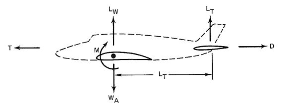
Any imbalance in these forces results in descent or climb in the vertical plane or faster or slower speed in the horizontal plane. A change in the lift of the elevator initiates climb or descent. Thrust, T, is the prime contributor for climb or descent and faster or slower speed, However, a balance of forces must always be maintained for horizontal flight or steady rate oi climb or descent.
4.6 WIND-TUNNEL TESTING OF PARACHUTES
Wind tunnels are an effective tool for testing air vehicles and air-vehicle components and have been used successfully for testing parachutes and parachute systems. Experience has shown that certain rules apply for the wind-tunnel testing of parachutes. Small parachutes manufactured from textiles cannot be made sufficiently similar to large parachutes in geometric design and flexibility, Lightweight material. required to obtain design similarity, is difficult to manufacture or is unobtainable.
One cardinal rule has been established through many years of parachute wind-tunnel testing: A modification that changes the performance of a model parachute in wind-tunnel testing produces the same type and percentage of performance change in a large parachute. This rule is true for drag. stability, and opening-force characteristics.
4.6.1 Blowers
The simple air blower (Figure 4-14) is a proven tool for preliminary parachute testing of a chiefly qualitative nature. Unless special test conditions prevail, parachutes tested should be a minimum of 1.5 to 2 feet in diameter to obtain meaningful results.
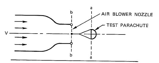
An air blower is a preliminary test too! because it permits quick parachute• configuration changes and excellent visual observation.
4.6.2 Open-Throat, No-Return Wind Tunnels
The open-throat, no-return wind tunnel shown in Figure 4-15 permits exact measurements if parachutes of sufficient size are used. Parachutes 3 feet or more in diameter are well suited for obtaining good, quantitative test results.
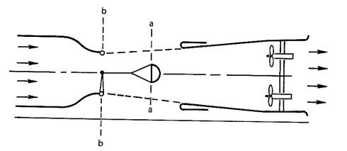
In air blowers and open-throat wind tunnels, the velocity at the skirt of the parachute (Section a-a of Figures 4-14 and 4-15) is lower than the velocity at the nozzle exit of the wind tunnel (Section b-b of Figures 4-14 and 4-15), Care must be taken to measure the parachute test velocity at Section a-a and not at Section b-b, the customary attachment point for airfoils and models.
Wind tunnels frequently cannot test at the descent velocity of most main parachutes of 20 to 30 feet per second. Obtaining proper test results at this low is hampered by a poor velocity distribution in the wind-tunnel-test section, and by the weight of the test parachute. The latter has a tendency to pull the parachute downward, thereby providing a negative angle of attack, lusting unstable parachutes at higher presents the problem that the drag coefficient CD, of unstable parachutes is sensitive. The drag coefficient of unstable parachutes is described in section 5.2.
An open-throat wind tunnel permits quick changes in parachute configuration, such as changing the suspension and reefing line lengths. Large open-throat wind tunnels that are not sealed against outside elements suffer atmospheric problems such as fog formation in the test section.
4.6.3 Closed-Throat, Full-Return Wind Tunnel
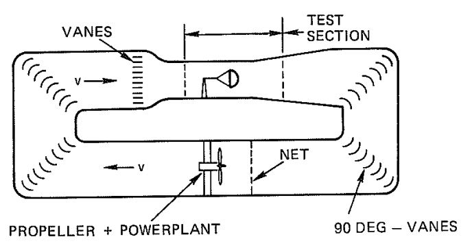
Figure 4-16 is a drawing of a full-return, closed-throat wind tunnel. fic full-return, closed-throat wind tunnel is generally considered best suited for obtaining good. qualitative, aerodynamic data, since it has a uniform distribution in the test section. A disadvantage is the difficulty in gaining access to the test section for changing the parachute configuration.
4.6.4 General Comments for Wind-Tunnel Testing of Parachutes
1. Parachute models for wind-tunnel testing should be as large and as similar as possible in geometry and flexibility to full-scale parachutes. Parachutes of less than 1.5 feet in diameter usually lack geometric similarity and material flexibility, which results in inflation characteristics and dissimilar inflated shapes.
2. The finished dimensions of model parachutes must be measured as accurately as possible to determine the nominal diameter, Do, and the surface area, So. Model parachutes will shrink from 5 to 10% during manufacture because of sewing take-up, which results in a notable difference in the dimensions between the drawing and the completed parachute.
3. Wind-tunnel tests of parachutes are excellent for comparing different models and modifications: also, they are the most effective means for measuring coefficients of lift, drag. and normal and tangential forces, as well as for determining the load coefficient, for infinite load.
4. In wind-tunnel tests, velocity decay does not occur during parachute inflation and operation; this is defined as testing under "infinite mass condition." First-stage drogue chutes and parachutes with a canopy loading, W/CDS. in excess of 100 lb/ft2 approach this condition. Low-canopy-loading main parachutes with rates of descent of 20 to 30 ft/s have a large velocity decay during opening, which requires careful interpretation of the opening-force data obtained in wind-tunnel tests.
5. In the past, to avoid wind-tunnel blockage and questionable test data. the diameter of a test parachute could not exceed about 5 to 6% of the wind-tunnel test section area. Recent Sandia investigations of single and clustered ribbon parachutes with wind-tunnel blockage ratios of up to 30% have resulted in correction methods that make it possible to test much larger parachutes (Reference 4.2).
4.7 REFERENCE MATERIAL
4.1 H. H. Hurt. Aerodynamics for Naval Aviators Navy Manual NAVWEPS 00 80T 80. Chief of Naval Operations, Aviation Training Division.
4.2 J, M. Macha and R J. Buffington. "Wall-Interference Corrections for Parachutes in a Closed Wind Tunnel." AIM Paper, April 1989. (AIM 89-0900-cp.) For readers interested in a more detailed study of aerodynamics, the following books are recommended.
For readers interested in a more detailed study of aerodynamics, the following books are recommended.
4.3 J, H, Dwinnel, Principle of Aerodynamics. McGraw-Hill Co., New York, 1949.
4.4 J. Morane. Introduction to Theoretical and Computational Aerodynamics. John Wiley & Sons.
4.5 R.S. Shevell. Fundamentals of Flight. Prentice-Hall. 1983.
4.6 J. D. Anderson, Jr. Introduction to Flights, ILS Engineering and History. McGraw-Hill Book co., New York 1978.
4.7 D. J. Cockrell. The Aerodynamics of Parachutes." AGARDograph No. 6295, available from NASA Langley Research Center, M/S 180, Hampton, Va., 236.


