Definitions: Difference between revisions
No edit summary |
No edit summary |
||
| Line 5: | Line 5: | ||
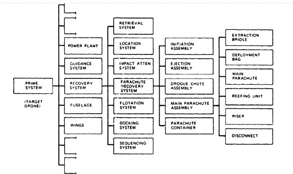
Although a parachute recovery system is a subsystem or even a subsystem of a prime system, as shown in Figure 2-1, common usage refers to all parachute recovery subsystems and assemblies as systems. Figure 2-1 also shows the typical breakdown structure of a target drone recovery system containing-in addition to the parachute recovery system--sequencing, impact attenuation, flotation, location, retrieval, and docking equipment. | Although a parachute recovery system is a subsystem or even a subsystem of a prime system, as shown in Figure 2-1, common usage refers to all parachute recovery subsystems and assemblies as systems. Figure 2-1 also shows the typical breakdown structure of a target drone recovery system containing-in addition to the parachute recovery system--sequencing, impact attenuation, flotation, location, retrieval, and docking equipment. | ||
[[File:2-1 system integration.jpg|center|System integration and components of a Parachute Recovery System]] | [[File:2-1 system integration.jpg|center|System integration and components of a Parachute Recovery System|598x598px]] | ||
Revision as of 20:34, 16 May 2024
Chapter 2: Recovery System Definitions and Descriptions
2.1 Recovery System Definitions
Defining the components and terminology of a parachute recovery system will help to avoid misunderstandings between Government agencies, prime contractors, and sub-contractors.
Although a parachute recovery system is a subsystem or even a subsystem of a prime system, as shown in Figure 2-1, common usage refers to all parachute recovery subsystems and assemblies as systems. Figure 2-1 also shows the typical breakdown structure of a target drone recovery system containing-in addition to the parachute recovery system--sequencing, impact attenuation, flotation, location, retrieval, and docking equipment.

Figure 2-1
Many parachute recovery systems contain fewer components than are listed in Figure 2-1. For example, an aircraft landing deceleration parachute system consists of a compartment in the aircraft with door actuators and the parachute disconnect mechanism, and, separately within the compartment, a parachute assembly comprising an ejectable pilot chute, pilot-chute bridle, brake parachute, brake-parachute deployment bag, and riser with disconnect clevis.
Figure 2-2 is a schematic of a typical ejection seat parachute assembly with descriptive nomenclature. Many variations of the assembly are possible: independent main-parachute deployment, stabilized high-altitude descent on the drogue chute, seat stabilization by attitude sensors and reaction control system (RCS), velocity-altitude control of the parachute deployment sequence, and man-seat separation. The variations may result in more or fewer components and different component arrangements.