Definitions: Difference between revisions
No edit summary |
No edit summary |
||
| Line 28: | Line 28: | ||
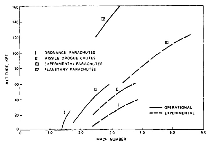
Figure 2-5 shows the approximate velocity and altitude boundaries of parachute systems that are presently in service or have been tested experimentally. Boundary limits are moved upward and outward as new materials are introduced that shift the aerodynamic heating limit to higher temperatures and make possible the recovery of heavier vehicles. Successful landings on Mars have been made, and vehicle landings by parachute on Venus and Jupiter are in preparation. | Figure 2-5 shows the approximate velocity and altitude boundaries of parachute systems that are presently in service or have been tested experimentally. Boundary limits are moved upward and outward as new materials are introduced that shift the aerodynamic heating limit to higher temperatures and make possible the recovery of heavier vehicles. Successful landings on Mars have been made, and vehicle landings by parachute on Venus and Jupiter are in preparation. | ||
[[File:Figure 2-5.jpg|center|frame|Figure 2-5: Aerodynamic Decelerator Performance Range (1990)]] | [[File:Figure 2-5.jpg|center|frame|Figure 2-5: Aerodynamic Decelerator Performance Range (1990)]] | ||
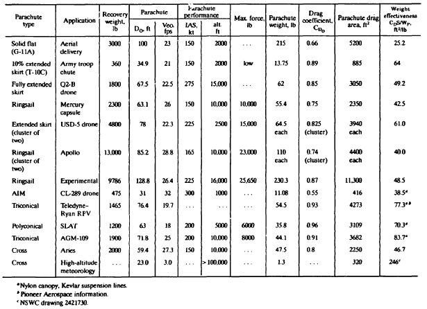
[[File:Table 8-2.jpg|center|frame|Drag Area/Weight Efficiency for Several Operational Parachutes ]] | |||
Revision as of 21:24, 31 May 2024
2.1 Recovery System Definitions
Defining the components and terminology of a parachute recovery system will help to avoid misunderstandings between Government agencies, prime contractors, and sub-contractors.
Although a parachute recovery system is a subsystem or even a subsystem of a prime system, common usage refers to all parachute recovery subsystems and assemblies as systems. Figure 2-1 also shows the typical breakdown structure of a target drone recovery system containing-in addition to the parachute recovery system--sequencing, impact attenuation, flotation, location, retrieval, and docking equipment.
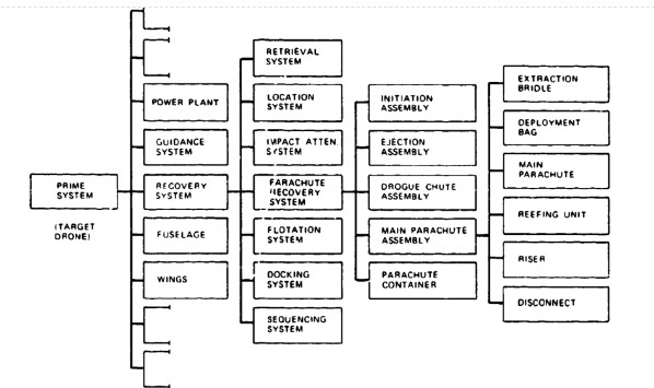
Many parachute recovery systems contain fewer components than are listed in Figure 2-1. For example, an aircraft landing deceleration parachute system consists of a compartment in the aircraft with door actuators and the parachute disconnect mechanism, and, separately within the compartment, a parachute assembly comprising an ejectable pilot chute, pilot-chute bridle, brake parachute, brake-parachute deployment bag, and riser with disconnect clevis.
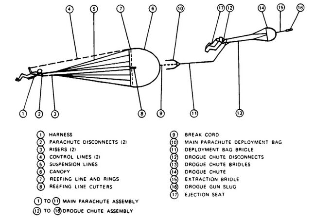
Figure 2-2 is a schematic of a typical ejection seat parachute assembly with descriptive nomenclature. Many variations of the assembly are possible: independent main-parachute deployment, stabilized high-altitude descent on the drogue chute, seat stabilization by attitude sensors and reaction control system (RCS), velocity-altitude control of the parachute deployment sequence, and man-seat separation. The variations may result in more or fewer components and different component arrangements.
2.2 PARACHUTE RECOVERY SYSTEM APPLICATIONS
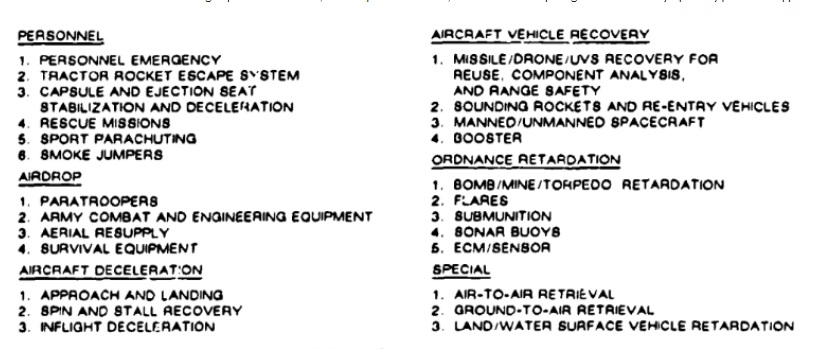
The first recorded development and application of parachute-type devices involved the lowering of animals, and occasionally humans, during fairs and carnivals in 14th- and 15th-century Siam and China. Parachute development in Europe and the United States began in the 18th century for use in exhibits and shows. The first application of parachutes for saving the lives of aviators occurred during World War I. Since that time, parachutes have been used for the rescue of aviators; for premeditated jumps of military and civilian personnel; and by sport parachutists, smoke jumpers, and paramedic jumpers.
An airdrop of military personnel and equipment is the final phase of transport to a theater of operation. Personnel and equipment must land uninjured, undamaged, and ready for action or use.
Aircraft in-flight and landing deceleration involves the termination of dangerous flight maneuvers, such as spin, deep stall, and high-speed flutter. In these cases, the parachute is disconnected after the aircraft reaches a controlled flight attitude. Many militaries) and some civilian aircraft use parachutes as landing brakes to shorten the landing roll and save tires and brakes.
Many ordnance devices, such as bombs, mines, torpedoes, and submunitions, are parachute-retarded to let the aircraft escape the effective range of the weapon, to stabilize and retard the weapon before water entry, to obtain antiricochet impact angles, and to obtain a desired splinter-distribution pattern after impact.
Air vehicle recovery includes termination of flight, and recovery for reuse of targets, unmanned vehicle systems, booster rockets, and manned and unmanned spacecraft. Some of these are recovered by the Midair Retrieval System (MARS).
Parachutes are also used to decelerate high-speed land vehicles, rescue speedboat crews, and decelerate ships. Figure 2-3 lists today's primary parachute applications.
2.3 Recovery System Boundaries
The application range of parachutes with regard to velocity and altitude was closely associated with the speed and altitude capability of aircraft until the 1950s. A research program conducted in the late 1940s and early 1950s established that parachutes could be used at supersonic speeds; parachutes developed specifically for supersonic application followed. Parachutes have been used successfully at speeds in excess of Mach 4.0, at altitudes up to the limits of the atmosphere, and at dynamic pressures to 15,000 psi. Parachutes have also been used to recover a rocket booster weighing 185,000 pounds. Figure 2.4 gives the required parachute performance envelopes for different applications.
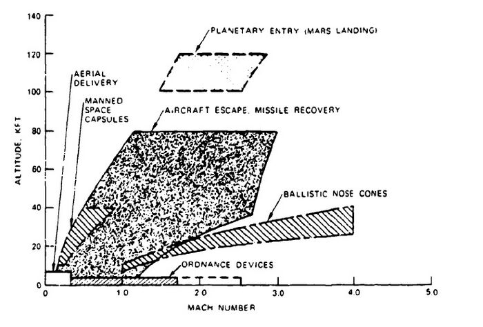
Figure 2-5 shows the approximate velocity and altitude boundaries of parachute systems that are presently in service or have been tested experimentally. Boundary limits are moved upward and outward as new materials are introduced that shift the aerodynamic heating limit to higher temperatures and make possible the recovery of heavier vehicles. Successful landings on Mars have been made, and vehicle landings by parachute on Venus and Jupiter are in preparation.
